Continue to Site

Welcome to our site!

Electro Tech is an online community (with over 170,000 members) who enjoy talking about and building electronic circuits, projects and gadgets. To participate you need to register. Registration is free. Click here to register now.

  • Welcome to our site! Electro Tech is an online community (with over 170,000 members) who enjoy talking about and building electronic circuits, projects and gadgets. To participate you need to register. Registration is free. Click here to register now.

Small signal to 5V output amp

Status
Not open for further replies.
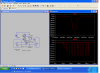
With no WIRE connected.

At PIN3 on 555 (disconnected from rest of the circuit). Nice square wave. Both FETS cool.

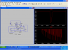
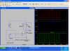
At PIN3 on 555 (Connected to the rest of the circuit). Distorted and small wave, PFET too hot to touch. NFET cool. Output Wave similar to PIN3.
 

Attachments

  • Graph.jpg
    Graph.jpg
    84.8 KB · Views: 176
Sure nice you have a scope. Let's try this so we don't burn things up.

Lets disconnect the 2 drains from each other and add a resistor ( 1K ) between them instead. That should limit the current.
It sounds like one of two things:
Either the N Channel is always on or
One of the speed up diodes is backwards. The way it is designed the FETs should turn on slow (thru the gate resistors) and turn off fast (Thru the diodes across the gate resistors). If that doesn't happen the current will be very high during switching.
 
I have access to Scopes, and other electronic stuff once a week, and they gave me a mini scope last week, brilliant.

Will there be any current with NO WIRE connected?

I am also wondering about the Diodes.

Does your simulator tell you when there are conflicts or errors? It didn't spot the GND error.
 
Diodes

Will there be any current with NO WIRE connected?
There will be a small current while one FET is turning off and the other is turning on. (first picture ~450ma)
I am also wondering about the Diodes.
If they are in backwards that would cause the problem you describe. Since the P Channel has the highest resistance it would get the hottest. (see 2nd picture for the very high current)
Does your simulator tell you when there are conflicts or errors? It didn't spot the GND error.
Sometimes it just won't run if it can't figure out the circuit, but usually you have to interpret the outputs to see if they are what you want. For example in the case of the ground the output went between ground and minus 12 instead of plus 12. I'm not sure it would really work that way or not.
 

Attachments

  • diodes.PNG
    diodes.PNG
    77.6 KB · Views: 172
  • Backwards.PNG
    Backwards.PNG
    77.9 KB · Views: 161
ok, thank you.

I see on the second picture you have turned the middle Diode around, is this the now correct way? I'll try it anyway, so watch out for smoke!!
 
NOoooooo. Hope you added the 1K first. That was just to show the the "shoot thru" current went up to 80 amps.
 
Ah, so that's why it got hot.

At one time I took the FETs out and there was a square wave at both Gates, but not with them in.
 
The diodes should be as in the original schematic. The resistor will just keep things cool.

What FET did you use for the P Channel?
 
Here is how the diodes work:

The gates of the FETs have capacitance, so by adding the resistors to the gates it slows down how fast they turn on. Then by putting the diode across the resistor it allows them to turn off quickly (Think of the diode shorting out the resistor in one direction). So for the NFET the positive going signal will be slowed down but the negative going will be fast thru the diode. The opposite is true of the P Channel (slow on the negative, fast on the positive). Without this setup when the 555 output changes state their will be a short for a small period of time when both FETs are on.
 
Ok, thanks.

I'll need to read it a few times to perhaps understand it. It's a bit advanced for me.

Can you answer a question?
If one end of the WIRE is connected to GND, and the other end to the FETs output, why is there a need for an N FET? I would have thought that when the PFET is ON, it would pull the other end of the WIRE up to 12V, then when it was off it would snap back to 0V-GND
 
Sure nice you have a scope. Let's try this so we don't burn things up.

Lets disconnect the 2 drains from each other and add a resistor ( 1K ) between them instead. That should limit the current.
It sounds like one of two things:
Either the N Channel is always on or
One of the speed up diodes is backwards. The way it is designed the FETs should turn on slow (thru the gate resistors) and turn off fast (Thru the diodes across the gate resistors). If that doesn't happen the current will be very high during switching.

If I connect a 1K resistor between the 2 Drains, which side of the resistor does the output Capacitor need to be?
 
Driver

I like your idea, but it has 2 problems:

The current thru the short wire will be to high.
The current thru the clamp diode (D1 in the circuit below) is to high.

If you can make the short wire twice as long it would work!

I would use the N Channel FET, it is better (higher current rating)

The problem with the other circuit I gave you is I used the values for the N Channel FET I gave you instead of the one you had which is slower to turn off.
 

Attachments

  • wire driver.PNG
    wire driver.PNG
    79.3 KB · Views: 152
I can just use this Amp for the long WIRE, and for most other WIREs I can use my less strong Amps.

I have been playing with the circuit + long WIRE, including only the PFET plus its Resistors and Diodes, but without the NFET +R+Ds. The PFET stayed cool, and there still wasn't enough signal. Do you think it was because of the PFET and Diode being not strong enough?

I used the PFET in the belief that the WIRE would be connected to 0V instead of 12V, and be safer, but now I don't think it matters.

Can you choose a different Diode as the one on the PNG is surface mount.

So does the FET current and Diode current change the WIRE signal strength? or is it the resistance of the WIRE that draws the Current, which makes the signal stronger?

I understand that FETs can be paralleled, so I presume I can simply stick one on the side of the FET in the circuit.
 
I can just use this Amp for the long WIRE, and for most other WIREs I can use my less strong Amps.

Cool

I have been playing with the circuit + long WIRE, including only the PFET plus its Resistors and Diodes, but without the NFET +R+Ds. The PFET stayed cool, and there still wasn't enough signal. Do you think it was because of the PFET and Diode being not strong enough?

It's hard to say without seeing the circuit.

I used the PFET in the belief that the WIRE would be connected to 0V instead of 12V, and be safer, but now I don't think it matters.

It doesn't matter, but if you use the NFET circuit and need more power it will be easier to modify.

Can you choose a different Diode as the one on the PNG is surface mount.

I think a SB540, 50 or 60 is fairly common.

So does the FET current and Diode current change the WIRE signal strength? or is it the resistance of the WIRE that draws the Current, which makes the signal stronger?

The FET and Diode just need to be capable of driving the maximum current which is determined by the resistance and inductance of the wire. We can increase the current by raising the voltage if we need to.

I understand that FETs can be paralleled, so I presume I can simply stick one on the side of the FET in the circuit.

If you use the N Channel it should be ok with 1.
 
It's hard to say without seeing the circuit.

It's your circuit #75 minus M2,R3,C1,D2.

It doesn't matter, but if you use the NFET circuit and need more power it will be easier to modify.

Will do.


I think a SB540, 50 or 60 is fairly common.

Found them.

The FET and Diode just need to be capable of driving the maximum current which is determined by the resistance and inductance of the wire. We can increase the current by raising the voltage if we need to.

OK.

If you use the N Channel it should be ok with 1.[/QUOTE]

Ok.

(P.S How do I get the shaded quote as your message?)
 
Last edited:
Status
Not open for further replies.

Latest threads

New Articles From Microcontroller Tips

Back
Top