Electro Tech is an online community (with over 170,000 members) who enjoy talking about and building electronic circuits, projects and gadgets. To participate you need to register. Registration is free. Click here to register now.
Welcome to our site! Electro Tech is an online community (with over 170,000 members) who enjoy talking about and building electronic circuits, projects and gadgets. To participate you need to register. Registration is free. Click here to register now.
So far,the main problem has been sensing a wide range from the COIL signal. (I hadn't realise the significance of the
'Inverse square law' before).
WIRE SIGNAL AND COIL: The signal generator gives quite a strong signal.
I can turn the WIRE signal down if the signal is too high, but if the signal is too low, I can't turn it up.
The COILS are good and can sense some signal at a 1Mtr +.
On my 'old' circuit the best range I could get at the A/D input was APP 2V to 3.5V this was too narrow for working.
Audioguru said it was because the LM324 chips don't work well at the high frequency of my circuit.
GOING INTO THE AMP CIRCUIT> I should be able to adjust the WIRE to give a COIL signal of somewhere between 0.2V to
2'ish'V However the signal can drop lower than 0.1 so that there is no control at all.
The circuit must be able to cope with the large range of COIL input voltages up to 10V, until the system has been set up.
COMING OUT OF THE AMP CIRCUIT> Once I have a good range from the Amp I think I could divide it to give: 0'ish'V to 5V
input to the A/D on the PIC. (The 5V might need clamping to stop A/D overload)
AT THE PIC: I have a set-up PIC that tells me (LEDS) what signal is sensed, so I can adjust the WIRE to give around A/D
2.5V.
Once working as above, The PIC has a programmed Deadband something like this: > < and I can widen or narrow the gap as I
wish, also there are delays on the forward/reversing of the Motor, for safety. (I've blown a few up, plus circuits).
Then the Motor will try to keep the COIL/WIRE distance to give an A/D of 2.5V.
I have just done some 'extreme' low voltage tests. Bear in mind that my test equipment isn't up to much!!
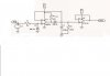
I have your circuit plus the attached 2n3819 pre amp. This is not connected to your circuit yet.
At the COIL the low voltage is 10mV. This, fed into your circuit did give a small voltage 0.05V. At the 2n3819 out the voltage is 40mV, so it has amplified 4X.
I am fairly sure I need to add this pre-amp. I tried connecting the pre-amp to your circuit but something isn't right.
Perhaps if I knew how to join the 2 together (coupling capacitors???), this might work.
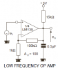
The new opamp circuit has a voltage gain of ONE (it has no amplification). Your Jfet circuit has A LOT OF VOLTAGE GAIN (lots of amplification).
Adding 2 resistors to an opamp increases its voltage gain to any amount you want, then you don't need the Jfet circuit.
But the schematic of the new opamp circuit was saved as a fuzzy JPG file type so I can't read the part number of the first opamp.
The Jpg is an enlargement from the .PNG file that Ronv posted, which was also difficult to read. I gueassed it is LM339 and that's what I have put in the test circuit.
I understood that the minimum that this can 'see' on it's input is 200mV if so then this is too small. The 2N3819 can 'see' much less, I think that's why it was suggested to me.
The LM339 is a comparator that does not have a frequency compensation capacitor like all opamps have so it should not be used as an opamp with negative feedback because it will oscillate.
There is an application for it as a very low frequency opamp circuit.
I don't understand why the Ronv circuit that I have in front of me is working, just as simulated in his attachment, where you say it won't work at that frequency?
It seems that if the LM339 is Indeed working ok, it still needs an addition to the front of it to be able to see the low voltages from the COIL inputs to the Amp.
I think if I could add the 2N3819 to the front of the amp, I could get it working, by turning down the WIRE signal to suit.
Ronv is using the LM339 comparator as an opamp in a "precision rectifier" circuit that has no voltage gain.
An opamp is supposed to be used, not a comparator.
Since it has a voltage gain of one, if the input signal has a peak of 50mV then if it works the output will have a DC peak of only 50mV.
The output opamp also has a gain of one so its output will also have a peak of only 50mV.
If the input has a peak of 5V then the output will have a peak of 5VDC.
Your right, the problem is with the range. If you increase the gain by adding an amplifier (or by increasing the gain of an op amp) the output will saturate when the signal is larger. If you can modify your firmware we could perhaps use a difference amplifier to only output the difference in the signals rather than having the micro try to do that. Then you could servo on 0 diffwence. If I understand you correctly you will always have a range of 1000:1. It can be 10mv to 10 volts or .1 volts to 100 volts if you amplify it. I assume you need to servo at all voltages in between?
If the WIRE signal strength is weak and the COIL is at Max distance from the WIRE 'say' 6inch the COIL might read 10mV.
If the WIRE signal strength is strong and the COIL is at MIN distance from the WIRE 'say' 1inch the COIL might read 10V.
Your circuit will work ok in most circumstances, but it needs to 'see' 10mV, and I don't think it goes quite that low.
If I could add some amplification (2N3819)to the front of it, and it was overloaded I could turn the WIRE signal down, so would work ok, as long as nothing popped while setting up.
I could make a rule that the WIRE is set low while setting up, then turn it up to suit.
So in use, only a fairly short range of signal is actually needed, a bit like tuning in to a radio.
Once set up to a particular WIRE, it will only need fine tuning.
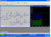
Here is a gain stage using your fet. Notice how it clips with higher input? If you can adjust this out I think you will be okay. It may be sensitive to noise so keep the leads short to your coils.
I've been 'playing' with the 2N3819 Fet, and it's S and D resistors. I can get App 50X from it, Does this sound correct? It seems sensitive and 'sees' 10mV and less, in fact I think it was picking up my radio!!
Next job to connect it to the rest of the circuit (A/D input on 16F819)
It certainly has plenty of range, Near 0V to about 9V, then it clips, but this is ok.
I think it will be fine without dividing LT1013 output voltage in 1/2, to give 5V, as long as the A/D will not damage with over voltage, while I lower the WIRE signal to give max 5V. If the A/D will damage, then perhaps I could clamp it at 5V, is this possible?
Sounds good. I think I would clamp the output of the 1013. Add a small resistor between the output of the 1013 and the a to d. (say 470 ohms). Then add a schottky diode (cathode to +5 and anode to the pic input pin). I think this will protect the a to d though I don't know the max input spec.
So far I have carried out tests with a short test WIRE, setting the signal using a home made COIL/Meter. Over the year or
so I have made different signal generators:
1/ Frequency timed approximately by a 555, and a few parts, no amplification.
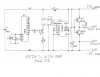
2/ The last one is Crystal controlled, and has 2X power Transistors for output amplification. This needs to be turned
down for shorter wires or it gets hot, and it is uneccessary.
Today I carried out a tests on the longest WIRE, and they were dissapointing, and not strong enough to work. So I think
I ought to make sure the Signals into the WIRE are good before proceeding. I don't have a schematic for the 555 circuit,
but it's about as simple as you can design. Here is the Schematic for the XTL controlled circuit.
I built the XTL circuit because the 555 one wasn't strong enough for longer WIREs. Todays test showed that there wasn't
much difference in the signals between both Signal WIRE circuits (with the XTL circuit full on). I had to place the COIL
on the WIRE to get anything. I have made note of the readings from COIL to output along the Amp circuit, and there are
some odd readings, i,e, high COIL input low Amp output.
Bear in mind my test equipment is not brilliant, me also!!
Any ideas, to test and maybe improve these WIRE signal circuits?
The Amp that you posted, complete with 2n3819 front end, is amplifying the COIL signal, being picked up from the WIRE, which is in a loop attached to a signal generator. Attached in the last message also others including a 555 timed one.
I tend to type COIL and WIRE in capitals so I can scan messages easier.
This site uses cookies to help personalise content, tailor your experience and to keep you logged in if you register.
By continuing to use this site, you are consenting to our use of cookies.

")