camerart
Well-Known Member
Hi,
I have a 18F4520 set up to read NMEA data, and show the result of a calculation, and works ok with a GPS module sending once/second. Obviously I am only getting one reading, as the GPS is stationary.
I need to check GPS movement, and have tried copying NMEA paragraphs (Paragraph = a second burst of sentences) and sending them to the PIC with a Teraterm macro/FTDI, sending paragraphs once/second. This is not working.
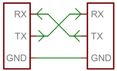
Both DATA signals are approx 3V, the FTDI can be changed to 5V.
I'm considering a MAX232.
Any ideas?
Camerart.
I have a 18F4520 set up to read NMEA data, and show the result of a calculation, and works ok with a GPS module sending once/second. Obviously I am only getting one reading, as the GPS is stationary.
I need to check GPS movement, and have tried copying NMEA paragraphs (Paragraph = a second burst of sentences) and sending them to the PIC with a Teraterm macro/FTDI, sending paragraphs once/second. This is not working.
Both DATA signals are approx 3V, the FTDI can be changed to 5V.
I'm considering a MAX232.
Any ideas?
Camerart.