Continue to Site

Welcome to our site!

Electro Tech is an online community (with over 170,000 members) who enjoy talking about and building electronic circuits, projects and gadgets. To participate you need to register. Registration is free. Click here to register now.

  • Welcome to our site! Electro Tech is an online community (with over 170,000 members) who enjoy talking about and building electronic circuits, projects and gadgets. To participate you need to register. Registration is free. Click here to register now.

Simple PNP switching problem

Status
Not open for further replies.

DirtyLude

Well-Known Member
Okay, I'm stuck on this. I don't have a very good knowledge of transistor theory, so it's likely I'm doing something basic wrong.

I'm using a TIP125 to switch a load. This is for a computer and I'm switching power to an inverter for cold cathode lighting. I would like it to be able to turn on and off the CCFL.

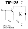
The TIP125 is switching the power side of the circuit and the base is connected to a uC that switches ground, to turn it on and off.

The whole thing works perfectly unless I connect the inverter to the circuit, then the inverter just stays on, or just switches the power faintly for a few seconds before going full on. If I connect a regular LED to the circuit rather than the inverter, the LED switches perfectly; ON/OFF. I checked with a multimeter while the LED was connected and the TIP125 is switching 12V/0V correctly.

So, I have no idea what I am doing wrong. Switches perfectly if just an LED is connected, does not switch, when the inverter is connected.
 
Should we guess, or are you going to attach your schematic?

The output of the uC goes up to only 5V doesn't it? The base of the TIP125 needs to be higher than 11V to turn off. How are you converting it?

If an LED turns on but the inverter doesn't then maybe the darlington transistor doesn't have enough base current.
What is the supply current of the inverter?
 
I thought that a schematic would be too simplistic. There's just the uC, a resistor to base, and the transistor switching the high side.

Okay, I am not certain about the supply current for the inverter. I will measure it, but I'm guessing it's about 500mA's or less.

I was under the impression that I did not need to turn 'OFF' the PNP by supplying current to the base, simply disconnecting it from ground would turn it 'OFF'. I will lower the base resistor from current 10k and see what happens.

Thanks you for your help.
 
What is disconnecting the base of the darlington transistor from the 0V or 5V output of the uC? The base needs to go to about 11V or higher to turn off.

What is connecting the 10k base resistor to 0V?

The datasheet for the TIP125 shows it saturating well with a base current that is 1/250th of the collector current. Your 10k resistor is too high for a 500mA load.
 
Well the uC output can sink, source, or turn off. Do I need to have something disconnect it? The uC is connecting the resistor to GND to turn it on. Like I said, there's nothing more interesting working here.

Why do I need 11v? I just lowered the resistor and with an error in soldering it didn't actually connect. When I connect the CCFL with the base left unconnected to anything, the CCFL is off, like I would expect.

I'm not understanding why I'm having a problem turning it off, but not on.
 
The base to emitter of the darlington transistor is two base-emitter diodes in series. The darlington has a very low input current so the base to emitter voltage is about 0.5V for each for a total of 1V. The emitter is connected to +12V so the base needs to be +11V or higher for it to turn off.

Some uC's have protection diodes on their input/outputs that stop external inputs from exceeding +5.7V. So the 10k resistor to the +11V base of the darlington has 11V - 5.7V= 5.3V across it which results in a base current of 0.53mA and is not turned off.

Let the uC drive another 10k resistor connected to the base of an NPN transistor with its emitter grounded. Then its open collector can turn the darlington on and off through the existing 10k resistor.
But the logic is inverted.
 
DirtyLude said:
If I connect a regular LED to the circuit rather than the inverter, the LED switches perfectly; ON/OFF. I checked with a multimeter while the LED was connected and the TIP125 is switching 12V/0V correctly.

Audioguru, though I agree completely to your theory of input protection diode biasing the PNP base to +5.6V, I cannot find any good explanation why it had worked for a LED with 0V is being measured.
 
Thanks. I will put an NPN between the uC and the base of the PNP.

I don't think it will help much, but here's the schema. I didn't do it before, because unfortunately when I changed computers I lost the original and full schematic for the control board I am working on.

**broken link removed**

Used an LED component, to represent the CCFL inverter.
 
The LED is burnt out without a current-limiting resistor. That's why you measured 12V then 0V at it.
Maybe the LED is made with a built-in current-limiting resistor for 12V?
If it worked with the LED then it should also work with the inverter.
 
audioguru said:
The LED is burnt out without a current-limiting resistor.

He doesn't mean, he's tried it with an LED, like he said the LED on the schematic represents the inverter.
 
Hero999 said:
He doesn't mean, he's tried it with an LED, like he said the LED on the schematic represents the inverter.
Exactly. When I used the LED I used a limiting resistor. When I say the LED turns on and off. I mean it actually cycles with the test pattern I programmed. It is not burned out.

audioguru said:
If it worked with the LED then it should also work with the inverter.
It doesn't. So I guess this all goes back to square one. Why doesn't it? It's stumping me, but then like I said, my transistor theory is not very good.
 
I'm sure it doesn't help either, but this is a picture of the board. Unforutunately the conformal coating makes the picture look kinda nasty. I put the conformal coating on after verifying that the PNP's worked with an LED. I assumed that would be fine. Looks like I jumped the gun on that one.

**broken link removed**
 
Russlk said:
I would put a resistor from base to emitter on the TIP125. Asking the darlington the turn off with an open base is asking for trouble.
The manufacturers are way ahead of you.
 

Attachments

  • TIP125.PNG
    TIP125.PNG
    5.7 KB · Views: 4,690
Do you have an insulating washer under the TIP125s? It doesn't look like you do in the case-controller-02.jpg picture. If not, the collectors are shorting to the ground plane on your PCB!
I would still put an NPN between the uC and the base of the PNP. BTW, what type of uC are you using?
 
There's conformal coating between the PCB and the TIP125. I sprayed it on pretty thick on both the PCB and the back of the TO220 before screwing it down, but currently there are no screws and the transistor is open air. I removed one of the transistors to do some tests on a breadboard.

I am using a Zilog Z8 Encore.

I will still try the NPN.
 
NPN -> PNP worked. Thanks for all your help, guys.

It made my control board look terrible though. I had to offload all of that part to proto board.
 
Russlk said:
I would put a resistor from base to emitter on the TIP125. Asking the darlington the turn off with an open base is asking for trouble.
audioguru said:
The manufacturers are way ahead of you.
tip125-png.9655

Why asking the darlington yo turn off with an open base is asking for trouble?
What's the purpose of the resistors?
How about the diode?
 
Last edited:
A low level transistor with an open base is turned on by heat due to leakage base current.
Transistors without a resistor to turn them off turn off very slowly.
The diode isn't used. It might be part of manufacturing.
 
audioguru said:
A low level transistor with an open base is turned on by heat due to leakage base current.
Transistors without a resistor to turn them off turn off very slowly.
The diode isn't used. It might be part of manufacturing.
What is low level transistor?
Resistors should be added in between the base and the collector? I've neer seen this type of circuit before. How about NPN type? also between the base and collector?

Thanks
 
Status
Not open for further replies.

New Articles From Microcontroller Tips

Back
Top