Continue to Site

Welcome to our site!

Electro Tech is an online community (with over 170,000 members) who enjoy talking about and building electronic circuits, projects and gadgets. To participate you need to register. Registration is free. Click here to register now.

  • Welcome to our site! Electro Tech is an online community (with over 170,000 members) who enjoy talking about and building electronic circuits, projects and gadgets. To participate you need to register. Registration is free. Click here to register now.

Shoe Box Radio Upgrade, cool ideas wanted

Status
Not open for further replies.
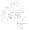
This is usually happens, I post something that everyone disagrees with and so eveyone stops posting. I have some more questions about the LM8650 though, in the datasheet for the positive power supply circuit, there is a part of the circuit that is outlined,

I can't figure out what that is for.
If it's mandatory for the proper opperation.
Or if it is mandatory, what values I should use.

The next thing is, I want to add a circuit that will turn the iPod on in the morning as an alarm, The problem is, in order to do this I need to solder a 32 pin connector into place and that task is prooving very difficuilt because the 32 pin connector is a SMT device. Any pointers on how I should do this. I may just end up going to the apple store and buying a 32 pin to audio converter, and just modifying it so my circuit can work the buttons. But it would still be nice to know how to solder a SMT. Thanks.
 
I've decided that just to be on the safe side concerning the battery life, I'm going to connect the battery to an ammeter and remove power from the clock to see how much current it draws from the battery. (it can't be much since it's a 9V right?)
 
The discontinued clock IC uses the mains frequency for its timing and to light the LEDs.
When it is battery powered then its LEDs do not light and it uses an internal RC oscillator for its timing.
It will draw 5mA to 7mA from the 9V battery.
I don't know if the alarm will work when it is powered from its backup battery.
 
Space Varmint, I took another look at your clock circuit that you showed me (PS: don't include your name in your schematic, at least not your real name) and I have concluded that you can use the MAX7219 to drive an LED display instead of an LCD display. The MAX7219 has a similar pin configuration as your AY0438. (you may want to double check though)

Here is the data sheet.

Yeah I forgot about that. I did it a long time ago, Everything but name has changed. No biggy. So wanting to try out that chip? It looks like it will work but would have to use two of them.
 
Yeah I forgot about that. I did it a long time ago, Everything but name has changed. No biggy. So wanting to try out that chip? It looks like it will work but would have to use two of them.

I thought that you might like that, but here's something else, you know how I said that I'm going to modify a 32 pin connector for controlling my iPod? I have made a simple circuit to do that, but the problem is that the more I look into the way that the connectors opperate, the more I've realised that a uC is going to be needed. Please don't give me the design just yet (I want to take a shot at making it myself). I do have one more question for you though, how much do you know about 8051 code?

The discontinued clock IC uses the mains frequency for its timing and to light the LEDs.
When it is battery powered then its LEDs do not light and it uses an internal RC oscillator for its timing.
It will draw 5mA to 7mA from the 9V battery.
I don't know if the alarm will work when it is powered from its backup battery.


The alarm does not work during battery backup, in my mind that's a good thing. The "LW filter" circuit is confusing to me though, I don't know if it's needed (my understanding is that it uses it to filter noise off of the mains) and if it is needed, I don't know what values to use for the parts (my assumtion is that the transistor could be a 3904).
 
Last edited:
I thought that you might like that, but here's something else, you know how I said that I'm going to modify a 32 pin connector for controlling my iPod? I have made a simple circuit to do that, but the problem is that the more I look into the way that the connectors opperate, the more I've realised that a uC is going to be needed. Please don't give me the design just yet (I want to take a shot at making it myself). I do have one more question for you though, how much do you know about 8051 code?

Yeah, I've done 8051 code and design and 8088, 80386ex and 80L188
 
You know Guru and anyone else interested. The dern regenerative receivers are just too unstable at least for what I was trying to do. I was trying to cover a portion of the short-wave band. The carrier, the way it jumps around in level is a bit of a pain. I suppose it could be controlled but I was looking for a good cheap design to receive mostly short-wave broadcast. So I'm trying a direct conversion. I just don't like the image frequency but suppose I will have to put up with it.

Anyway, question for the group. Anybody ever try using a differential amplifier circuit for a mixer? I think it would have distinct possibilities! You have two base (gate) inputs for the VFO and the rf signal input and it has a very high gain. I'm trying it out. Will let you know but any input is appreciated.
 
You have quite an extensive back round with programing. That's good news, because the micro-controller that I have is a DS2250-32-16, and it uses 8051 programing. I think that this is the pin out for the 32 pin (it may be a 30 pin) connector. **broken link removed** Here is a link that is similar to what I want to do: The dock. Here is a pic of what I would like to hack (I don't think that the same company makes it though) Oh well, ideas on how to go about his? The best I could come up with is some 555s and a 4017. Just about anything would be better. **broken link removed**
 
Last edited:
I briefed over it. What is it you want to do? You talking about the serial port? That stuff is built into PIC processors now days. It is also built into the Intel embedded processors. The 80188 and EX versions of the more advanced processors. The Pentiums are all embedded as well. When I used separate chips I used Nat'l Semiconductor going back to the NS16450 which was in the original IBM PC.
 
Think I made a terrible selection on the diff amp. I think my mixer products got snagged by common mode rejection.

The Diff amp mixer is used, where? I have never seen, but I have found papers on the subject. It seems as though it is important that the two transistors are matched in which case a single package pair would be used.

Here is link to one such mention. It appears to have some advantages over other mixer topologies but also some pitfalls as well. As in most cases with RF, there is always trade offs to be made.
Granted the author should have had the paper proof read, theory is still sound.
https://www.electro-tech-online.com/custompdfs/2010/03/Paper154-J_Sevova.pdf
 
Last edited:
I briefed over it. What is it you want to do?QUOTE]

I am tryinging to get the Audio Technica from the second picture (apple makes a similar one) and oppen it up and tie the uC to the internal electronics so that the rest of my circuit will work properly with the iPod (i.e. the alarm can turn the iPod on to wake someone up). I don't think that it should be too hard to do.
 
I came up with a cleaver idea. After poking around on the internet a little, I found some 30 pin connectors that are easiser to solder than the one that I was origonaly going to use, we can just use that to get the uC to interface directly with the iPod. I think that will be a lot easier and less expensive.

Just to give you some pointers on the specs of my uC, like I said it's a DS2250-32-16. It does not have an RTC installed in it, however I do have an RTC that could work with it, the DS12F887 (I'm not sure about the F digit but I do know that I'm right about the rest of the numbers). That RTC would be kind of good for something like this because it also has EEPROM built into it.

These are some questions for audioguru.

Can your FM transmiter be made with a 12V input?
Are the 2 variable cappacitors the same cappacitor?
Can I substitute the Vreg with an average 5V regulator?
 
The Diff amp mixer is used, where? I have never seen, but I have found papers on the subject. It seems as though it is important that the two transistors are matched in which case a single package pair would be used.

Here is link to one such mention. It appears to have some advantages over other mixer topologies but also some pitfalls as well. As in most cases with RF, there is always trade offs to be made.
Granted the author should have had the paper proof read, theory is still sound.
https://www.electro-tech-online.com/custompdfs/2010/03/Paper154-J_Sevova-1.pdf

Thanks Mike. You'll never believe it. I hooked up a transistor backwards...lol. I thought it might work. Even with it I figure I will need a post mixer amp.
 
I came up with a cleaver idea. After poking around on the internet a little, I found some 30 pin connectors that are easiser to solder than the one that I was origonaly going to use, we can just use that to get the uC to interface directly with the iPod. I think that will be a lot easier and less expensive.

Just to give you some pointers on the specs of my uC, like I said it's a DS2250-32-16. It does not have an RTC installed in it, however I do have an RTC that could work with it, the DS12F887 (I'm not sure about the F digit but I do know that I'm right about the rest of the numbers). That RTC would be kind of good for something like this because it also has EEPROM built into it.


These are some questions for audioguru.

Can your FM transmiter be made with a 12V input?
Are the 2 variable cappacitors the same cappacitor?
Can I substitute the Vreg with an average 5V regulator?

What frequency is the RTC? Are you familiar with CTCs or Intel 8253? The 8253 has 3 RTCs in it and is commonly used.
 
These are some questions for audioguru.

Can your FM transmiter be made with a 12V input?
The RF amplifier transistor will probably burn up. Add a 7809 voltage regulator.

Are the 2 variable capacitors the same capacitor?
They are separate trimmer capacitors. The oscillator capacitor changes the tuned frequency. The RF amplifier capacitor is peaked and can be peaked in the middle of the FM broadcast band (98MHz) and the RF amplifier still works at any frequency in the FM broadcast band.

Can I substitute the Vreg with an average 5V regulator?
I used a low-dropout 5V regulator because my 9V battery can drop to 6V as it is used. You can use a 78L05 regulator if you want.

My FM transmitter is mono. Why not make a modern stereo FM transmitter instead?
 
Last edited:
Thanks Audioguru, I've thought about using a modern transmitter circuit, but your circuit is easier for me to make than some of those circuits. I'm going to work on the cirucit this weekend, however I may need you to point out how to make the 2 0.1uH inductors in the circuit. (after I check to see if I have some)

Space Varmint, at first glance I could not find a clock speed on the RTC, but you may have better luck finding it than me so I'm going to post the data sheet. DS12C887
 
Well I have some good news, and bad news. The good news is, I think that I have the correct configuration for my µC. The bad news is, I have no 0.1µH, and radio shack (the fastest source of parts) does not have any.

So audioguru, sorry to be a pain, but can you tell me how to make the inductors from scratch?

Space Varmint, I have the circuit ready, can you tell me if this is right or not? If it's wrong, can you please tell me what I did wrong? All I did with the circuit was try to get the DS2250 to use the DS12C887 for extra memory.
 

Attachments

  • DS2250-DS12c887..jpg
    DS2250-DS12c887..jpg
    242.5 KB · Views: 245
The bad news is, I have no 0.1µH, and radio shack (the fastest source of parts) does not have any.
RadioShack sells cell phones and kids toys, not modern electronic parts.

So audioguru, sorry to be a pain, but can you tell me how to make the inductors from scratch?
I used 1mm enamelled wire from a two-way speaker's crossover network and wound nine or ten turns around a dowel like this:
 

Attachments

  • FM coil..PNG
    FM coil..PNG
    33.1 KB · Views: 343
Status
Not open for further replies.

Latest threads

New Articles From Microcontroller Tips

Back
Top