Electro Tech is an online community (with over 170,000 members) who enjoy talking about and building electronic circuits, projects and gadgets. To participate you need to register. Registration is free. Click here to register now.
Welcome to our site! Electro Tech is an online community (with over 170,000 members) who enjoy talking about and building electronic circuits, projects and gadgets. To participate you need to register. Registration is free. Click here to register now.
It's really, really ghetto, but when I show it to people, I think that it adds some level of appreciation to the whole thing, just because it looks home made.
And I have another good reason for not putting a more powerful amp in the box, the one that's in their now has an FM receiver built in, I can't even get the transmiter from this thread.
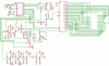
You want the transmitter too? I have been wanting to revise an old one I did but I want to shrink the PLL way down which I have made so many since then I could do it rather quickly. I could do the whole PLL with a small PIC processor and a Motorola MC145170 and one prescaler a VCO and a DC amp and loop filter. The rest is done and puts out about a half watt. I even built a 40 watt amplifier and used it for a while. This was some time ago. Here is the non processor PLL circuit I made:
Well I forgot. I did it so long ago that it is in Orcad SDT so can't post it. But the one I would like to do looks will look something like this. I don't see the prescaler so it's obvious it's unfinished:
edit*
Wait, I think I was looking at the data sheet for the PLL chip (MC145170) and found that it has an internal prescaler. I have to check again.
You don't have to, the company that made the amp did that for me!
But about the VU meter, I have made the circuit below before, but it only works if you have the audio going straight into the inputs, as soon as I attached an 8 ohm speaker, the meter stopped working. I'm not sure if the problem would be the same with something like an LM3915 or LM3916, but that's the reason why I was talking about adding another LM386 amplifier to the inputs. Then technical, the VU meter and the speaker are not even part of the same circuit (or something like that)
I was worried about the same thing happening to your FM transmitter.
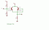
Sounds like you need a good buffer amplifier. Tap off the output with something like a Darlington pair or just a common collector amplifier. Then run the output to the speaker as you would normally do.
Wait a minute. Did you have sound before? I would buffer the VU if you did. Sometimes if the speaker pulls a big load you can use a good power transistor which comes as a Darlinton, like a TIP120. Feed the speaker with that. Maybe 2.2K to the VCC and 100 ohms from emitter to ground. Of course the collector is straight to VCC. I have driven 8 ohm speakers with this off 741 OP amps audio output. With 5 volt VCC. Capacitively couple the speaker.
If you don't have one try some power transistors in a configuration like this. But use maybe 10K or less in the base circuit and lower emitter resistance. Don't forget to capacitively couple it off the emitter. If you got audio in you should hear something on the speaker. Check the audio into the base.
Now, in the circuit I posted for the VU meter, there are 2 inputs, should I just connect the negative input to ground. Although, they seem to have the inputs mixed up, I'm wondering if I should switch the inputs and I might get better results. I had a friend recommend just using decoupling capacitors on the output of the amp, but when I tested this, I got a high distortion and some problems involving the VU meter not working properly.
Now, in the circuit I posted for the VU meter, there are 2 inputs, should I just connect the negative input to ground. Although, they seem to have the inputs mixed up, I'm wondering if I should switch the inputs and I might get better results. I had a friend recommend just using decoupling capacitors on the output of the amp, but when I tested this, I got a high distortion and some problems involving the VU meter not working properly.
I never used one of those. I see a single audio input so I would assume you need ground. Tell ya, you need to get Audioguru on this. He is a pro! I was just giving suggestions because it sounded like you had audio and the VU loaded it down. Originally I suggested buffereing it. You still didn't answer me if you had audio before or not???
Your LM324 VU meter is the same as an LM3914 voltmeter IC. It can be very sensitive when the 50k trimpot is set to max resistance.
You should use an LM3915 VU meter IC instead that can be set for a max input of 1.25V peak or more. It might need a preamp.
I never used one of those. I see a single audio input so I would assume you need ground. Tell ya, you need to get Audioguru on this. He is a pro! I was just giving suggestions because it sounded like you had audio and the VU loaded it down. Originally I suggested buffereing it. You still didn't answer me if you had audio before or not???
OK, do you have a scope? It sounds like you had distortion. Was your audio loaded down? If the audio was weak, than the speaker could have been loading the audio down in which case a buffer amp would work very well for you. What it does is not only convert the impedance down to a lower Z to help match the very low 8 ohms impedance, but also isolates the source of the signal from the heavy loading of the speaker. Do you have a set of head phones? Most of the time head phones will not load your signal so severely. If you hook up some head phones instead of a speaker and the signal sounds clearer and less distorted, than that will tell you you are over loading the signal and you could use a buffer to help. What size is this speaker you are using? If it is large it will load your signal down even more. So start there and don't worry about the display just yet. Get your audio right. And as I said before, Audioguru is the pro with stuff like this. I have never met anyone with nearly the knowledge he has about audio electronics but he can be kinda harsh with new comers so just let it slide. He can really help out allot.
Is the power amplifier the low power Sanyo one or the low power LM386?
The size of a speaker has nothing to do with its amount of loading. Its impedance determines its loading effect.
Most audio power amplifiers are designed to drive an 8 ohm speaker properly.
The LM324 VU meter's inputs are wrong. The 33k resistor is the input and 0V must be connected to ground, not the positive supply.
This site uses cookies to help personalise content, tailor your experience and to keep you logged in if you register.
By continuing to use this site, you are consenting to our use of cookies.