Electro Tech is an online community (with over 170,000 members) who enjoy talking about and building electronic circuits, projects and gadgets. To participate you need to register. Registration is free. Click here to register now.
Welcome to our site! Electro Tech is an online community (with over 170,000 members) who enjoy talking about and building electronic circuits, projects and gadgets. To participate you need to register. Registration is free. Click here to register now.
Your code (now) works fine in the simulator and so I would guess that your problem is hardware. Do you have MCLR tied high? Can you do something simple like just lighting the LEDs?
Actually I'm using low pin count demo board supplied with PIC Kit 2, and I'm touching a wire from Vdd to RA2 and then connect it to GND manualy, but as you said that it runs well on simulation I'll check the hardware, by the way, I am tryiing to simulate the codes but don't know how to use stimulus , I have selected pin/register actions from stimulus window then add a signal for RA2 (that has generated a coloumn for RA2), then I ticked repeat and set it for 5 sec,what else I need to do, I been through help file but that is rather confusing. I'm sorry that I ask too much but I'm studying correspondently so internet is the only source where I can learn from and thank you all for the help !
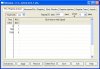
I just setup the stimulus as shown in the attachment and then do apply. I then set a breakpoint on the first instruction after org 4 (movwf temp) and run it with F9. If you view the SFRs you can see port C increment.
Hi c360,
Touching A2 to Ground and Vcc with a piece of wire is about the worst thing you could do to generate an Interrupt!. You will generate multiple interrupts.
The only reliable way is to use a momentary switch or push button, connect A2 to Vcc with a 4K7 resistor and use the switch to connect A2 to ground.
The switch should also be debounced by using a simple resistor/capacitor filter between the switch and A2.
How could you be able to set "restart at 0" while there are only 500 and 1500 in time coloumn, I am having problem setting "restart at 0", I have added "0" in time coloumn and respectively put "1" in RA2 coloumn (I could have explained better by sending a pic., how did you copy the whole window as thumbline ?), but that did'nt work, in SFR port c shows all zeros.
...........Thanks eric I have a push to on switch at hand ,will try that and tell you
However careful you are touching a PIC input pin with a piece of wire, chances are you will get multiple contacts and the PIC will act in a unpredictable way.
There are software routines that are used to debounce switch contacts that are being 'polled' by the program, but for switches which generate an Interrupt I have found it better to add hardware debouncing.
EDIT:
I would also use hardware debouncing [opt#2] when using the PIC Timers as counters with external clocking inputs.
How could you be able to set "restart at 0" while there are only 500 and 1500 in time coloumn, I am having problem setting "restart at 0", I have added "0" in time coloumn and respectively put "1" in RA2 coloumn (I could have explained better by sending a pic., how did you copy the whole window as thumbline ?), but that did'nt work, in SFR port c shows all zeros.
I knew this will happen
O.K. ,when I go to the restart box the drope out menu appears and it has only two values 500 and 1500 so, how did you select "0" because the value (0) must be in the drope out menu but as I said it (0) is not there. If you still don't get what I'm referring to then tell me how did you make thumbline of the whole stimulus window because I don't know how to do that otherwise I would have sent you a picture of mine stimulus window which I hope have served better, so please tell me how to save stimulus window in picture (JPEG or any other) format so as to post it on blog (just as you did to explain me), I hope this will be understandable.
Oh! and thank you eric for your ckt this will take some time to build ,so will tell you later about that.
Mine one does'nt have "0" so, I did something awkward, I have added 0 in time coloumn and for this 0 time I set RA2 to 1 and then I have 0 in the dropeout menu..........., oh god I can't go more easy than this in words ,Mike please tell me how did you attach the picture of stimulus window in your last post (I know how to attach a picture, but don't know how to copy an active window as a picture)
Mine one does'nt have "0" so, I did something awkward, I have added 0 in time coloumn and for this 0 time I set RA2 to 1 and then I have 0 in the dropeout menu..........., oh god I can't go more easy than this in words ,Mike please tell me how did you attach the picture of stimulus window in your last post (I know how to attach a picture, but don't know how to copy an active window as a picture)
To copy the screen, press the key that has "Prt Scr/SysRq" (next to scroll lock) on it and the screen is copied to the clipboard. Go into your favourite graphics program and paste it.
O.K. so this is what I have done to get "0" in restart, is it right to do so?
And the simulatio still does'nt work, after doing whatever in the thumbline I clicked apply then svaed the workbook, so this supposed to work.
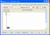
I guess you were using single step (F8). If you set a breakpoint as shown below, by double clicking in the grey border, then you can press f9 and the program will run until an interrupt occurs.
I know that but, pressing F9 with a break point runs progarmme only for first interrupt(as it should be) and then when I press agin F9 to cross over break point the whole MPLAB gets hang, only animation runs good but, that takes too much time.
I know that but, pressing F9 with a break point runs progarmme only for first interrupt(as it should be) and then when I press agin F9 to cross over break point the whole MPLAB gets hang, only animation runs good but, that takes too much time.
It shouldn't do that, it should stop at the breakpoint every time you press F9. It might be worth downloading and installing the latest version.
Does it now work on the hardware. A good way to generate interrupts is to turn on the WPUs (WPUA=2 and OPTION.7 = 0) and then just ground the pin. The debounce problem shouldn't matter, it will just jump a few counts.
This site uses cookies to help personalise content, tailor your experience and to keep you logged in if you register.
By continuing to use this site, you are consenting to our use of cookies.

")