Continue to Site

Welcome to our site!

Electro Tech is an online community (with over 170,000 members) who enjoy talking about and building electronic circuits, projects and gadgets. To participate you need to register. Registration is free. Click here to register now.

  • Welcome to our site! Electro Tech is an online community (with over 170,000 members) who enjoy talking about and building electronic circuits, projects and gadgets. To participate you need to register. Registration is free. Click here to register now.

Setting ROHM BH1414K IC Circuit to 75us Pre-emphasis Curve

Status
Not open for further replies.
R3 and R4 are supposed to be 51k ohms then C3 and C4 should be 1000pF for 50us and should be 1500pf for 75us.
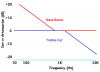
The bass frequencies are absolutely flat from about 13Hz up to where the pre-emphasis boosts the levels and 2.6Hz is at -3dB since the input capacitors are 1uF and they feed 51K + 10k. So there is no bass boost.
Changing the pre-emphasis from 50us to 75us boosts high frequencies more and does not affect bass frequencies.
Okay, I changed those two capacitors to 1500pF, but here is what is driving me nuts, before the change, I had some issues with the BASS being intense at times, but now the BASS is way over whelming, I never had to reduce the LOW frequency pots on the mixing board to almost -25 dB before I changed these capacitors, now I do! The BASS is now killing the stereo carrier to the point the MIDS and HIGHs are almost non-existent do to the reduction of the over all volume.
I am sure the capacitors are 1500pF, but I almost want to say I changed the pre-emphasis to 50us not 75us.
I would think the MIDS at the very least would be the over-whelming frequency, but this is not the case, the BASS is now the dominant frequency and the mids and highs are almost blocked out for some reason.
Besides those two capacitors, is there other parts that should also be changed?
If I created an off air recording and I kept the three EQ pots on the mixer LOW, MID and HIGH at 0dB you would definitely have to agree, the BASS frequencies are so dominate, the music is almost muffled. If I increase the MID and HIGH to make up the difference, I have to almost go to +12dB before the MIDS start to show up and the HIGHS are almost non-existent even at +12dB and even then they are not there in a lot of the songs!
What's up with that?
Bruce.
 
Last edited:
Pre-emphasis has no effect on bass frequencies. It simply boosts high frequencies so that the de-emphasis in all FM radios reduces the high frequencies back down to normal.
 
If you can only compare base to treble, then a reduction on treble sounds like an increase in base.
But he said the treble sounds are "almost non-existent", not just reduced. Even if the pre-emphasis does nothing then the de-emphasis in an FM radio is only a simple RC that reduces the highs, it does not eliminate them.
 
If the pre-emphasis capacitor is 10x too big then almost all audio frequencies will be boosted then the de-emphasis in an FM radio will reduce the frequencies. De-emphasis not severe, it is only one RC (6dB per octave).
 
AudioGuru,
You are right. This is the transmitter side.
How about the cap is 1/10 the right value. There is not much boost in high frequencies. So on the receiver there is a big reduction in treble which sounds some thing like the base is too much.
 
Are you sure you have the right part? Maybe 10X bigger than you think?
Here is a photo of the package the capacitors came in, of course they are too small to present a decent close up image of. The foot print is slightly larger than the original parts, but the company told me the capacitor size was 0805 and that is what I ordered. Unfortunately, none of the caps are marked, not even the original ones that were on the printed circuit board of the transmitter.
(Note: Please view post #31 below, it has images of the capacitors we are discussing.)

IMG_20160118_020425.jpg
 
Last edited:
This is the best I can do for a photo of the capacitors.
The loose ones are the original parts taken from the transmitter, the 2 in the tape, are duplicates of the ones I replaced the originals with. Note the two empty capsules in the tape.
Hope this helps.
Note: I do realize the new ones are larger than the original parts, I ordered them with a 0805 footprint because I was told that that is the size I needed for the new parts. Perhaps the new ones are the wrong size? Or perhaps the manufacturer was wrong with their recommendation?
IMG_20160118_022520.jpg
 
Last edited:
AudioGuru pointed out this is on the transmitter side. So if the cap was 150pF then you will have little high frequencies.
OR
If one side of the capacitor was not soldered then there is no capacitor and little high frequencies.

You said too much base. Which might be the same as saying too little high frequencies.

I got a box of capacitors form DigiKey.com that are 1/10 of the value marked on the package. I have a meter.
 
-40dB is a lot of level reduction, -60dB is complete elimination. The highs are not cut much if the pre-emphasis capacitor is missing.
I think that bass boost sounds completely different to treble cut as shown on my graph:
 

Attachments

  • bass boost and treble cut.png
    bass boost and treble cut.png
    20.4 KB · Views: 267
I seriously think there is an issue with those capacitors, I don't know if the size of replacements being larger than the original ones plays a factor here.
One major issue I find wrong with the industries decision to go with SMD/SMT circuit boards is the lack of identifying information on capacitors!

Clearly, we see that resistors are marked with identifying numbers, but electrolytic and coupling capacitors for the most part are unmarked.

How is one to know for sure what the values are?

Looking at my photos above, how can we tell what physical size the original capacitors are? Certainly if the replacements in the tape above are 0805, the originals are quite a bit smaller and actually fit in the circuit better than the replacement ones.

Is it possible to check dielectric values of SMD/SMT coupling/filter capacitors with a VOM meter, or is a 'capacitance meter' a must have to check for actual component capacitance?

I am wondering if experimenting with the value of the first 1uf electrolytic capacitor, the resistor/capacitor pre-emphassis network and the final resistor before the BH1414K audio input stage can make the audio quality better?

Can anyone point me to any published information in regards to experimentation with various values in this circuit?

I would be willing to read anything, white papers included, that offers an improved frequency response.

Bruce.
 
Many digital multimeters measure capacitance.

Pre-emphasis was added to FM transmitters to boost high frequencies. Then corresponding de-emphasis was added to all FM radios to bring the frequency response back to normal and the hiss in the reception is reduced.
75us was used before 50us so they are different. If you use an American 75us radio with a European 50us transmitter then the radio produces muffled high frequencies. If you use a 50us European radio with an American 75us transmitter then the radio produces excessive high frequencies.

The input capacitor in the FM transmitter feeding a resistance produces a highpass filter that cuts frequencies below its calculated cutoff frequency. The 1uF that feeds the 51k plus 10k resistors produces a -3dB cutoff frequency at 2.6Hz. Then frequencies are absolutely flat down to 13Hz. I would use a 470nF capacitor then frequencies would rolloff below 27Hz.

The "final resistor" which is the 10k before the audio input limits boost at ultrasonic frequencies that interfere with the 19kHz pilot and the stereo sidebands (23khz to 53khz) and it must not be changed.
 
470nF huh?

I do have a digital Micronta (Radio Shack) item number 22-184 multi-meter. I have never tried using it to check capacitors, that is besides electrolytic types, not sure if it works on regular caps or not. It only has DC volts, AC volts, Diode mode, K Ohm, DC mA and AC mA, so perhaps my meter lacks the abilty to check capacitance values.

I am just not sure how to determine the correct foot print for the 470nF caps. I learned electronics basics when surface mount technology wasn't even thought of yet, so this is all new to me.

Bruce.
 
Is there any other input on this rare subject?

I say rare, because I honestly have not seen many topics out there covering this topic.

Is a 470nF cap a better choice then a 1500pF cap is for better frequency response?

Bruce.
 
There are no other threads about FM pre-emphasis because "it was carved in stone" many years ago. It is either 50us for Europe and Australia or is 75us for North America. I do not know what it is in the Orient.

You are mixing up the capacitors. The pre-emphasis treble frequencies boost capacitor is 1000pF for 50us and is 1500pF for 75us. The audio input coupling capacitor determines which low frequencies are passed and is 1uF polarized for the datasheet and for the circuit you have but I suggested that 470nF (almost half of 1uF) would also pass all audio frequencies.

The BH1414 is not perfect, it makes a compromise with its audio 19kHz and 38kHz lowpass filter. It gradually cuts audio frequencies above 10kHz instead of sharply cutting above 15kHz. Then high audio frequencies from 10kHz to 15khz are not as crisp and sizzling as they should be when heard on an FM radio.
 
the HIGHS are almost non-existent even
Here is a pre-emphasis (in the transmitter) and de-emphasis (in the receiver).
Blue = Pre-emphasis
Green = total.
upload_2016-1-22_16-19-39.png

What would happen if the 1500pf was not in place. (0pf)
The high frequencies are almost gone.
upload_2016-1-22_16-23-32.png

Here is 1500pf was actually 150pf. Very little high frequencies.
upload_2016-1-22_16-24-50.png
 
-12dB to -14dB is not much cut but the lowpass filters in the IC reduce 15kHz about 3dB more for a total cut of -15dB to -18dB at 15kHz.
Actually -30dB produces little output and -60dB is non existant.
 
Status
Not open for further replies.

Latest threads

New Articles From Microcontroller Tips

Back
Top