Continue to Site

Welcome to our site!

Electro Tech is an online community (with over 170,000 members) who enjoy talking about and building electronic circuits, projects and gadgets. To participate you need to register. Registration is free. Click here to register now.

  • Welcome to our site! Electro Tech is an online community (with over 170,000 members) who enjoy talking about and building electronic circuits, projects and gadgets. To participate you need to register. Registration is free. Click here to register now.

Setting ROHM BH1414K IC Circuit to 75us Pre-emphasis Curve

Status
Not open for further replies.

MrBruce1959

New Member
Hello all I am new here and hope I am posting this in the right area of this forum board.

I am trying to figure out how to set the pre-emphasis curve on the BH1414K Wireless Audio Link IC to 75 microseconds so the audio is compatible with my FM radio which uses 75 Microsecond De-Emphasis.

There is no schematic available to the public and the capacitors which are SMD types have no markings, therefore I can not tell what their values are. I do know some of the resistors are marked 513 which are 51K Ohms.

I contacted the manufacturer and they mentioned two capacitors had to be changed to 1500pF because by default the pre-emphasis is set to 50us.

Here is a readily available data sheet I found for the BH1414K IC chip https://pira.cz/pdf/bh1414k.pdf

Below is a photo of the chip on my circuit board.
At the bottom left of the photo is the left channel circuit and to the right is the right channel circuit.

1-png.95528


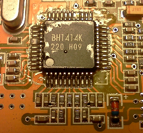
Does anyone have any clue as to what has to be changed for the correct 75us pre-emphasis curve?
Sorry for my dumb question, but I am new to this part of the learning curve.

Bruce.
 

Attachments

  • 1.png
    1.png
    512.9 KB · Views: 1,949
Last edited:
The 50 usec pre-emphasis was used for TV sound receivers. The bandwidth for TV sound was I think up to 10kHz.
The pre-emphasis of 75 usec was used for audio FM transmission up to 15khz.
If you are using the circuit for an intercom type of application, I would suggest you dont worry too much about the difference in the de-emphasis. The time constant is C x R. So your TV module has 50 x 10^-6 = 51 x 10^3 x C ^ 10^6 (in micro-farad). You can then multiply that value by 1 1/2.
The result is 0.001 microfarad for 50 usec and 0.0015 for 75 usec.
hope this helps.
 
Here is the inputs (pin 5,7). The op-amp and R1 is inside the part. R2,3 and C1,2 are out side.
The graph is the gain in db from 10hz to 20khz.
The dotted line is phase shift.
upload_2015-11-24_7-11-30.png
 
Here are the two curves for 1000pF and 1500pF.
So you can add a 470pF on top of the 1000pF cap or replace the cap.
upload_2015-11-24_7-46-51.png
 
I doubt you would even notice that subtle difference. I thought 50us was for european FM radio and 75us was US?
 
I doubt you would even notice that subtle difference. I thought 50us was for european FM radio and 75us was US?
You are correct 75 microseconds is used as the Pre-emphasis in the USA.

In China they use 50us Pre-emphasis therefore some of the FM transmitter circuits are set by default at 50us Pre-emphasis, which does not work well on FM stereo receivers in the USA.

I want this transmitter pre-emphasis to be at 75us pre-emphasis not 50us. I am not looking to modify a receiver's de-emphasis, just the transmitters pre-emphasis.

I am looking into some of the answers I have already received, plus I received a detailed data sheet from ROHM for the BH1414K IC chip.

I can not republish this sheet but they show a 1000p capacitor in parallel with a 51K resistor also showing a 1 electrolytic capacitor feeding both. I not sure if that is 1 uf or not and I will have to check the audio input circuits to see if there is an electrolytic capacitor just before the r/c circuit.

Bruce.
 
Last edited:
Look at post #3 and #4. I have the values for both pre-emphasis. 1000pf or 1500pf
Yes it is 1uF. That is for low frequency roll off.
 
Okay I am uploading an image of the part numbers in a map, the one that the seller sent to me referring to the capacitors that needed to be changed, which are C3 and C4 need to be changed to 1500pF, the resistor values in that R/C circuit are 51k Ohm, there also appears to be a SMD capacitor just before the R/C circuit which is C1 and C2, I can not tell if that is a electrolytic capacitor or not, but it is in the blown up photo I am including below showing greater detail of the circuit board and the numbers printed on those resistors. ( For that please see image #2)

IC 2.png
123.png


Hopefully these images will give greater detail a precise answer and in the end help anyone else who is researching this same issue.

Bruce.
 
@ Ronsimpson
According to the ROHM data book on the BH1414K IC chip, it says:

Quote: for example, to set the pre-emphasis to 50us, make C2 = 1000pF, R1 = 51K Ohm and R2 = 10 K Ohm.

The numbers you used above in my map would result in 50us pre-emphasis, not 75us, which is what I am trying to set the pre-emphasis to.

Please see these images below that back up my point these images were photographed from the ROHM Co. manual for the BH1414K chip.

Read what it says above the graph.

Those values you gave me would result in 50 microsecond pre-emphasis if the ROHM data book is correct. I need 75 microseconds not 50 microseconds.

Or perhaps you were just providing what the current values are on my circuit board, then I can understand, that it is set to 50us and changing those 1000pF caps to 1500pF would in fact change it to 75us, is this correct?
Bruce.
 
Last edited:
Okay here's my last question.

The seller said the specs on the SMD 1500pF capacitor is
Specification:

0805 footprint
1500pF ±5%

In choosing a SMD 1500pF replacement device I see mention of multi-layer (MLCC), X5R, C0G, Y5V etcetera, I am curious in this application where I am replacing the capacitors C3 and C4 what type of SMD 1500pF capacitor best suites this type of application? I am looking for opinions.
Bruce.
 
Look at these curves of temperature and capacitance in %.
For your application you want NPO but X7R will work.
Don't use Y5V or Z5U they are for power supply bypass.
You product is used indoors and maybe the temperature problem is not so important but.......
You could choose the wrong cap and it works fine at 24C (room temp) but at 0C you go from 1500pF back to 1000pF. LOL
2012031333617445.JPG
 
The 50 usec pre-emphasis was used for TV sound receivers. The bandwidth for TV sound was I think up to 10kHz.
Wrong and wrong.
USA invented FM and broadcasted it first a long time ago. Sound sources in those days had poor high frequency output levels so they decided to use a large amount of high frequency boost on the pre-emphasis which was 75us. USA TV audio also uses 75us.
When Europe began broadcasting FM they found that the high frequency boost was too much when modern audio sources were used so they reduced it to 50us and the same for their TV audio.
 
The issue of compatibility between a 50µs pre-emphasis transmitter, and 75µs de-emphasis receiver, and vice versa was discussed in great detail here:
https://www.radiomuseum.org/forum/fm_pre_emphasis_and_de_emphasis.html
It's interesting reading, but the executive summary is: It's probably not worth the effort of replacing SMD capacitors.
If you leave the pre-emphasis at 50µs on the BH1414K, then you'll end up with a 3.5 db bass boost at the receiver. Most people like more bass, so it may be a good thing. Otherwise, you can turn the bass down a bit on your receiver. Considering how heavily doctored present day recorded music is, 3.5 db of extra bass probably won't be noticed.
 
I disagree with the article. Pre-emphasis boosts high frequencies. De-emphasis cuts the high frequencies that were boosted back down to normal. Bass is not affected. The wrong pre-emphasis/de-emphasis results in muffled high frequencies like turning down the treble tone control on your stereo which of course will be noticed unless you are deaf. Bass boost is different.

If you "turn the bass down a bit on your receiver" then you end up with cut highs and cut lows and an awful sound something like a telephone call. (Nasal sound: "What? Did you say six, fix, or chicks?")
To temporarily fix it, simply turn up the treble tone control a bit.
 
Okay time for an update.
I have replaced C3 and C4 with a set of 1500pF 100v 2% Vishay multilayer ceramic MLCC SMD RoHS compliant capacitors from Mouser Electronics.
The result is for some reason that the low frequencies seem to be VERY dominate compared to the Mid to High frequencies on an FM receiver.
I have had to reduce the LOW frequency on the Mixing board in order to prevent BASS over drive.
Now let me get this straight, 75µs pre-emphasis is supposed to pass more of the higher frequencies and the de-emphasis is supposed to filter those frequencies to produce normal audio frequency response, right?

I am wondering if a 1500pF capacitor is the correct component for this 75µs result. It seems to have increased the BASS spectrum more than when there was a 1000pF capacitor in the circuit beforehand.
I do not have any equipment on hand to properly diagnose the results, so I can accurately tell whether I have 75µs pre-emphasis or not. I almost feel like the result is 50µs not 75µs.

Any thoughts on this? Is anyone totally familiar with this BH1414K IC chip?
Below is one formula for this chip from the data sheet.

upload_2016-1-5_20-55-48.png
 
R3 and R4 are supposed to be 51k ohms then C3 and C4 should be 1000pF for 50us and should be 1500pf for 75us.
The bass frequencies are absolutely flat from about 13Hz up to where the pre-emphasis boosts the levels and 2.6Hz is at -3dB since the input capacitors are 1uF and they feed 51K + 10k. So there is no bass boost.
Changing the pre-emphasis from 50us to 75us boosts high frequencies more and does not affect bass frequencies.
 
Status
Not open for further replies.

New Articles From Microcontroller Tips

Back
Top