Electro Tech is an online community (with over 170,000 members) who enjoy talking about and building electronic circuits, projects and gadgets. To participate you need to register. Registration is free. Click here to register now.
Welcome to our site! Electro Tech is an online community (with over 170,000 members) who enjoy talking about and building electronic circuits, projects and gadgets. To participate you need to register. Registration is free. Click here to register now.
Hi BryWY,
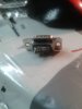
I assume the picture 002926.jpg is the original cable that you damaged and the connector in the picture is the female end that plus into the computer. Start by using your multimeter on a low ohms range to identify which pins the wires go to on the cable and make a table. You have not given any information on the nature of the damage to the male end. Unless it has been totally destroyed it should be possible to identify which colour wire goes to which pin. You may have to very carefully cut through the plastic moulding with a craft knife just shaving of a bit at a time until you can identify which wires go to which pins. If this is not possible for example the connector has been totally destroyed under a 100 tone press then I suggest this approach. Measure the voltage both at the PC end and the plotter end with respect to pin 5 (Ground.) of all the other the other pins on the connector and make a table for each end . (Include the polarity of the voltages.) When you have done this post the two tables. From this we should be able to tell if it is a straight through or crossover cable.
From your post #23 it looks like DTR from the computer is linked to provide DCD and DSR to the computer. On the assumption that it is a straight through cable I think the end of the original cable should be connected to the male end as follows.
Pin 1 N/C
Pin 2 Red
Pin 3 Yellow
Pin 4 Brown (Probably not required.)
Pin 5 Green
Pin 6 N/C
Pin 7 Blue
Pin 8 White
Pin 9 N/C
This May work but trying to identify the connections on the original male end would be a better solution.
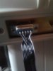
With reference to post #25 I was hoping to identify the colours of the wires going to the pins on the male end but it looks like they have broken off right at the pins. In post #27 I mean to use your old cable (Still with the female end attached.) and solder a male connector to the end of the cable that has broken off from the original male end.
You made a couple of measurements that to me indicate a NULL modem cable.
I really want to warn you how the pins go. Pay attention to the numbering.
The top one, is probably the most likely to work: **broken link removed**
If you know anything about the plotter, such as:
DTE/DCE
Software/hardware handshaking - what type DTR/DSR or CTS/RTS
The attempt to look at the unconnected voltages with respect to SG at the pins is to identify the port as a DTE or DCE.
If 5 & 3 or 5 &2 both had voltages on them at the computer and the plotter a straight through cable would not work.
Voltages at DTE or DCE would tell you in a real situation which type of device it is.
To give you an idea of how things work:
1. DTE/DCE tell each other that the device has power
2. RTS/CTS are hardware handshaking signals
3. TXD/RXD are data
4. SG is signal ground
Only 3 signals are required SG, TXD and RXD if software handshaking is employed.
I've seen real messes with 1 and 2. Like reversal of roles and bad assignments.
There are two other signals.
RI - ring indicator and CD - Carrier detect
RI is a signal telling you the phone is ringing
CD is a signal that the modem has carrier.
One of the RTS/CTS signals says - Answer the phone
SO it like ring(RI), answer phone (RTS?). wait for Carrier(CD), CTS
So, there were ways to disable "modem control" in software or make a few jumper connections to disable modem control.
So DTR/DSR put the modem and or computer offline.
DTE - Data terminal Equipment and DCE Data Carrier Equipment (The phone companies modem)
This was all implemented in a 25 pin connector. IBM came along and made a 9 pin connector. the 25 pin connector was used for the printer instead of the Centronics connector.
To really make this make sense, I'd have to verify the directions of the signals.
That's why I really wanted you do do some measuring from pin 5.
The IBM male side should be well known as to what it is. I still need a cheat sheet.
I will attempt to get more info on the able Pinout sequence today. Just have a small volt ohm meter cant figure how to measure negative currents accurately.
A few voltage reading would have helped stuff out a lot.
There were a few way to do this:
Know the pinouts
Use a straight thru and then a modem cable
Use a break-out box and instantly figure out the connections and make them accordingly in the box.
To make matters even more interesting, there are RJ45 and RJ50 serial cables. Some were cleverly designed that you could use a cross/straight to change the cable type. An RJ45 has 8 pins and an RJ50 has 10 pins.
Dis you try Desay and do you have the manual for it?
Some one on the web contacted this guy and said he had an answer back in < hr. dave@desaypc.com
Max.
From your test in post #23 it is not a full null modem cable that provides full handshaking. This is because on the female connector (Computer end) you say that pins 1 (DCD, 4 (DTR) & 6 (DSR) are connected together. This means that the connector on the computer end is cheating the full handshake . Ronsimpson in post #2 gave you the wiring diagram for a null modem cable. Normally a null modem cable would have a female connector on both ends. In post #24 I asked you to measure the voltages on all the pins with respect to pin 5 (Ground) at both ends. We know that at the computer end that pin 3 will be transmit so it will be between - 5 volts and -20 volts with respect to pin 5. If we knew the voltages on pins 2 and 3 at the plotter end we would know definitely if a straight cable or a null modem cable is required.
This site uses cookies to help personalise content, tailor your experience and to keep you logged in if you register.
By continuing to use this site, you are consenting to our use of cookies.