Continue to Site

Welcome to our site!

Electro Tech is an online community (with over 170,000 members) who enjoy talking about and building electronic circuits, projects and gadgets. To participate you need to register. Registration is free. Click here to register now.

  • Welcome to our site! Electro Tech is an online community (with over 170,000 members) who enjoy talking about and building electronic circuits, projects and gadgets. To participate you need to register. Registration is free. Click here to register now.

"serial port to PIC 16F84" sample code

Status
Not open for further replies.

wejos

Member
Hi guys,


Can you show me please the simplest way to receive a character from the serial port to my PIC 16F84.

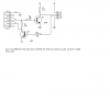
I have the schematic below. I can't use its original code because I don't
have a servo. What is more important to me right now is turning a LED on or off. So pressing "A" on the keyboard should cause a LED to light up, or maybe when you press "B" it does the opposite.

I understand that there are so many tutorials out there, mostly require using MAX232 and I still don't have that IC yet. I am going to play with them when I have bought one. Right now, this is the schematic that I'll be using.

**broken link removed**
 
Check my tutorial, although it uses the MAX232 because it's software serial (as needed by your antique 16F84) it's trivial to alter the polarity to use as in your circuit.
 
I am already using your software. I used it on my first project, which is turning on and off a LED. Your program works like a charm. Thank you.
 
You can use use this for the max232 it not as good but it works
 

Attachments

  • home made max232.PNG
    home made max232.PNG
    17.8 KB · Views: 2,160
forgive me since this is the first time I'm building this wonderful chips. i just wonder where pins 1234 go in pic 16f84?
 
thanks man. i'll buy the parts this afternoon. i will tinker with it tonight. again thanks.

one more thing, how am I going to interface the max232 schematic and the 16f84 schematic as shown in this diagram?

**broken link removed**

It's from the tutorial of this page, **broken link removed**

Should it be like this?

16f84----->max232----->serial port

The PIC TXD, 5V DSR, 5V DTR, PIC RXD, which is found at the right side of the schematic (PIC16F84) of that tutorial, should be connected to the which pin(s) of the MAX232? And which pins of the MAX232 will go to the serial port? I have not found any TXD, DSR, DTR, RXD from the datasheet of PIC16F84.

I really can't picture what's going on in there. please give me a lecture lols.
 
I guess i had missed the "hardware" hyperlink when I read your tutorial. I am building it tomorrow after I bought the parts.

You think it will work with my type of PIC?

Thanks a lot.
 
I guess i had missed the "hardware" hyperlink when I read your tutorial. I am building it tomorrow after I bought the parts.

You think it will work with my type of PIC?

Yes, you just have to make a few very slight changes, but it's the same 14 bit core - and the 16F628 was the replacement for the 16F84 last century.
 
Last century :eek: lols

I managed to borrow some MAX232 and will use your RS232 schematic.

Thanks Nigel.
 
Last century :eek: lols

It's not a joke - it's now 2009 and the 16F84 was declared obselete back in the 1990's, and replaced by the 16F628. It's since been reintroduced (at a higher price than the superior 16F628), due to loads of people still trying to order it, despite it having a much inferior specification.
 
It's not a joke - it's now 2009 and the 16F84 was declared obselete back in the 1990's, and replaced by the 16F628. It's since been reintroduced (at a higher price than the superior 16F628), due to loads of people still trying to order it, despite it having a much inferior specification.

Well after I'm familiar enough with the "84" model I will definitely move to "628".

Hey I'm learning a little bit of something everyday thanks to you all.
 
hi, every body! im student in Viet Nam

im beginning to learn PIC
Now i have just received a exercise from my teacher.
the exercise show that:
" design the system connect RS 232 uses 16F877"
temperature sensor( or var resistors) ---> f877---> rs 232---> monitor (use visual basic).
i didnt know what to do.
help me about it, pls!
if u have documents, please sent to me follow email:
phandinh1508@gmail.com
thanks a lot.
 
Status
Not open for further replies.

New Articles From Microcontroller Tips

Back
Top