Continue to Site

Welcome to our site!

Electro Tech is an online community (with over 170,000 members) who enjoy talking about and building electronic circuits, projects and gadgets. To participate you need to register. Registration is free. Click here to register now.

  • Welcome to our site! Electro Tech is an online community (with over 170,000 members) who enjoy talking about and building electronic circuits, projects and gadgets. To participate you need to register. Registration is free. Click here to register now.

School Bell Controller Final Project - PIC16F628A

Status
Not open for further replies.

Gayan Soyza

Active Member
Hi!

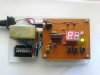
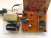
I just want to show you all a project I recently made, it named as SCHOOL BELL CONTROLLER designed under a PIC 16F 628A.

The purpose to build this project is its fully automatically controlling the bell in each school periods. So no need manually ring the bell in each period by the user or no need a computer program to operate the Bell.

Even if this can done with a simple timer IC or from counters (without a microcontroller)
It’s hard to add more options or displays to that to work the circuit very accurately.

So I planned to do like this way.

**broken link removed**

Operating the School bell controller?
1. Switch on the power or press the RST button to wake up.
2. When it comes to the PERIOD SELECT mode (P-) press COUNT UP button.

Then you will see this period numbers in the display at each press in COUNT UP button.

Here in a school we have total of eight periods with an interval after the fourth period.
Period length is 40 minutes and the interval is 30 minutes. This period lengths never change.

P1 = Period One – 40 Minutes
P2 = Period Two - 40 Minutes
P3 = Period Three - 40 Minutes
P4 = Period Four - 40 Minutes
IN = Interval - 30 Minutes
P5 = Period Five - 40 Minutes
P6 = Period Six - 40 Minutes
P7 = Period Seven - 40 Minutes
P8 = Period Eight - 40 Minutes
LB = Last Bell - (School Over

3. Select from which period you want to start the bell to ring.

(Let say you want to start the bell to ring from the second period then you must select P2 and press the SET button)

4. Then you will automatically come to the START TIME select mode (T-).

(What is this START TIME? – It means the exact time required to ring the selected period.)

For example: If the PERIOD 2 bell must ring at 8.30 AM. Now time is 7.40 AM.
So it needs 50 Minutes to ring the P2 period bell.)

This time can select by the user by pressing the COUNT UP button.

5. Select required TIME for the period and press the SET button to start the count down timer.

Now the operation has finished. Bell controller has been turned ON.

You can see the COUNT DOWN timer is working. (By looking at the count down timer can see whether it is working correctly or not)

In our example when it reaches to 8.30AM the bell rings for 5 seconds while displaying the P2 that shows the PERIOD 2 has been just started. After 5 seconds again it shows the count down timer (default is 40 MINS) for next periods. So and so it’s repeating to the end.

If the operator has forgotten to switch on the bell. For example now its 10 AM all he wants to do is SELECT the appropriate PERIOD for that time and set the START TIME. That’s all.
Some fancy features

*Manual Mode – anytime operator can ring the bell manually while the circuit is running.
*Any time START operation – operator can switch ON the circuit at any time or can adjust if it is inaccurate.
*COUNT DOWN - timer to check the accuracy or whether it is working correctly.
*Period notification -In each bell ring displays the correspond period.
*Display check – to check the two segments working correctly when power up.
*Automatically turn off - After last bell automatically turn off feature.
*Battery backup
 

Attachments

  • Layer1 - Control Panel.JPG
    Layer1 - Control Panel.JPG
    38 KB · Views: 3,986
  • Layer2 - Power Section.JPG
    Layer2 - Power Section.JPG
    51.2 KB · Views: 2,644
  • Bell Controller.PNG
    Bell Controller.PNG
    46.2 KB · Views: 2,399
Last edited:
hi gayan,

Looks good to me.

What's the PP3 battery for??

Do you have a box/enclosure for the pcb/display assembly?

Are those little white clouds on the circuit diagram , puffs of smoke?? :rolleyes:

Regards
 
Last edited:
Something to consider,
Use a 32768 hz watch crystal instead of the 4mhz crystal.
The wee 32khz will not only run at much lower power than 4mhz its also more accurate and easier to divide into seconds (use timer 0 and 1:32 prescaler for an exact 1 second overflow)
 
I like the circuit diagram.. Looks very cool. What did you use to make it?

Nice application, and well thought out.. 10/10 :D
 
blueroomelectronics said:
Something to consider,
Use a 32768 hz watch crystal instead of the 4mhz crystal.
The wee 32khz will not only run at much lower power than 4mhz its also more accurate and easier to divide into seconds (use timer 0 and 1:32 prescaler for an exact 1 second overflow)
I've heard that using a crystal as oscillation clock, at the same time another crystal is used at T0CK1 for counter. But I haven't seen anyone is using this, just heard about this.
 
Thank you Guys.

Hi Eric

This battery for the backup power supply if the AC power turns OFF.
Also there is a small DIP switch in the layer2 board to turn ON/OFF the battery back up.

9V battery can supply the circuit for 8 HRS until school over. I have dropped down its voltage to 5.1V.After last bell circuit enters to the SLEEP mode.

If no AC power the AC Bell also not working. But the circuit is running until the power comes. For sudden AC mains fall offs or the delay when shifting to the generator this battery very useful.

For the time being I don’t have an enclosure. I’m planning to build one. Just now I found a plastic sheet shop.

Puffs of smoke are call outs :D

Hi blueroomelectronics

The low power crystal is good, but due to unavailability of that 32 KHz I shifted to standard 4 MHz.

Otherwise I have to sacrifice a working wrist watch for this project :rolleyes:

In overall, considering power, spacing, coding, accuracy the watch crystal is ideal.
 
Too bad the 32KHz crystal is a hard to get where you are. They are very delicate and might be a trick to desolder.
TMR1 can use the 32KHz and your PIC could run from internal RC , you can even put it to sleep and TMR1 will wake it up when it overflows (2seconds or multiples of 2sec)

Could run for days. Also make sure your LEDs are really off.
 
Looks like someone already wants your good grades. :rolleyes:
 
Nice going, Gayan.
Next time you want to implement a timer or a clock consider using the mains as your clock source. It is highly regulated throughout the day, and is readilly available. Even crystals wander a bit due to temperature variations. Power your circuit off a simple AC wall wart. Tap off the power-in jack, before the rectifier. Run this voltage through a 1N4148 signal diode (or similar, watch the polarity!) and a two resistor voltage divider to get it down to 5V or less. Use a serial resistor, 1K Ohm or so, inline to the PIC pin, to protect the PIC from the occasional AC spike. Run this 50 or 60 Hz signal to an internal comparator (the '628A has two) set to the appropriate Vref. Every time the rising wave hits the Vref setting an interrupt can be used to increment a software counter. If interrupts are not what you want, simply poll the comparator's flag bit to detect when the threshold has been reached and then follow through in your code.

Of course you will have to add a rectifier, filter caps and regulator, but that's the trade off for a simple clock source that has successfully run wall clocks pretty accurately since Tesla convinced people to use AC generators to supply power.

'Luck in your project.
kenjj
 
I personally don't like using the mains as a frequency source because it might go wrong if I decide to run it from an inverter or in another country. Also other countries might not have such a procise frequency as the US and Europe; I don't know how accurate it is in Colombo, Sri Lanka.
 
Very nice Gayan! Perhaps you could also ring the bell at the end of the forty minute periods and allow a time between periods to get to the next class.
 
Hi Kenjj

I went through your idea. It helped me in my upcoming project.
I put your idea other way.
It means taking AC mains as the CLOCK SOURCE or as a SIGNAL to detect whether the AC mains have stable 230V/50Hz value, and if it has come to this value (230V/50Hz) can provide the output. If not settle (not reached) triggering a false signal.
Because here we have a very poor mains supply.
Also here AVG TEMP = 28 C no too much cool & no too much hot.
I checked the accuracy with some real time clocks almost perfect in this circuit. The circuit runs maximum 6 hours per day. So for 6 hours accuracy percentage is almost full.
 
Hi Sig239

I had your idea in the very first time before designing this circuit.
But here the period change time is grabbing from the next period. Also in earlier manual systems there’s no bell rings in period change times.
Sometimes in the upper school classes two periods time take as a one period. This called double periods.
If somebody needs a bell ring in between the period change time can develop easily. But here I didn’t add that.
 
Status
Not open for further replies.

Latest threads

New Articles From Microcontroller Tips

Back
Top