Electro Tech is an online community (with over 170,000 members) who enjoy talking about and building electronic circuits, projects and gadgets. To participate you need to register. Registration is free. Click here to register now.
Welcome to our site! Electro Tech is an online community (with over 170,000 members) who enjoy talking about and building electronic circuits, projects and gadgets. To participate you need to register. Registration is free. Click here to register now.
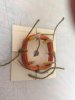
I had to cut through the old winding to free it from the stator, but I did get it out in one piece so I have a good idea of the size and shape. It seems to be a double U shape .. ..with the curve of the U bent outwards to meet a soft metal clip on the outside of the stator.
I'm full of apprehension, not least because I will have to apply mains voltage to test the measure of my success; but I've bought enough wire to have several attempts, if necessary.
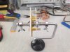
I've actually started rewinding today, how successfully I'm not sure yet.
The pictures give a bit of a blow by blow account as far as I've got, but I've ground to a halt because I need some heat resistant braid tubing and some wire to replace the connections between the winding and the brush contacts and I don't have anything suitable in stock.
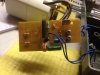
The frame the winder is on is what I use for winding new line onto my fishing reels, worked quite well. The string around the winding is just a temporary 'keep it all in place' until I'm ready to put the transformer tape and card formers back on.
I suspect there will not be any further action until the new year now, however, any advice or improvements would be greatly appreciated.
Are you putting any tension on the wire as you wind it? I understand that for transformers, tension is used to get a dense winding. I am not sure about motors, but I suspect the same consideration might apply.
I ran the wire through my finger tips as it was winding to keep it to the shape of the former and prevent any loops, but nothing more than that. Given that the wire is only 0.25mm, I would be concerned about tension stretching the wire causing a breach of the enamelling if too much were applied.
Another question, not related to the winding ... ... ..
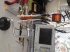
The motor is for a small circular saw and is connected to a small PCB, which I think is probably for speed control ... ..
What are the 2 identical components on the LH end of the pcb in the picture .. ? They are resistor like in size and shape, but have only one black ring midway.
Another question, not related to the winding ... ... ..
The motor is for a small circular saw and is connected to a small PCB, which I think is probably for speed control ... ..
What are the 2 identical components on the LH end of the pcb in the picture .. ? They are resistor like in size and shape, but have only one black ring midway.
I have seen many of those on the PCB's that accompanied our reagents. The chip often included calibration data and serial numbers that the instrument read to be sure we were using only "authorized" reagents.
I just assumed the engineers who designed the board wanted it to look more complex than it was. And/or didn't know how to route a board with only 2 layers.
Well Google .. .. that fountain of all info .. .. pertinent or otherwise .. .. .. says that they were created when automated board population was introduced because the machine more readily identified and handled a resistor size/style component rather than a piece of wire.
Sounds quite plausible if you say it quickly .. .. .
Assuming someone who can route a small ship on a double-sided board actually needs them. BTW, I use them in Eagle when routing, because it is easier than defining a jumper, much less make one, when using SMD components.
I can see a valid argument if you're using the same board for several different circuits where a resistance is not required for certain instances .. .. to substitute a zero ohms in place of another 'valued' resistor to complete the circuit would be easier than a wire jumper.
I've not got into Eagle at all. I use a piece of software called 'Circuit wizard' which I like a lot .. .. and .. .. .. I avoid SMD like the plague ! Through hole is fiddly enough for me !
This site uses cookies to help personalise content, tailor your experience and to keep you logged in if you register.
By continuing to use this site, you are consenting to our use of cookies.