Continue to Site

Welcome to our site!

Electro Tech is an online community (with over 170,000 members) who enjoy talking about and building electronic circuits, projects and gadgets. To participate you need to register. Registration is free. Click here to register now.

  • Welcome to our site! Electro Tech is an online community (with over 170,000 members) who enjoy talking about and building electronic circuits, projects and gadgets. To participate you need to register. Registration is free. Click here to register now.

Rewinding a Small AC Motor

Status
Not open for further replies.

Musicmanager

Well-Known Member
Hi Guys

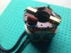
I've recently acquired a modellers table circular saw that would be great for cutting PCB blanks. I paid next to nothing for it so I wasn't surprised when it didn't run. A close internal inspection revealed a small circuit board which had suffered some serious 'tampering' and careless soldering, so I tidied it up somewhat and then tried again, but no luck.
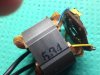
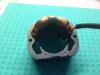
I've now discovered that one side of the motor stator coil is fractured .. .. .. when I removed the commutator I found a small piece of spring steel embedded in one of the stator coils, cutting through several winding strands.

I've removed the coil, counted the windings, measured the wire .. .. .. but ..

Do you think to rewind the coil is a realistic undertaking for a novice - I've never done one before ... or should I try and get it done by a professional ?

A replacement motor is not an option ..!

S
 

Attachments

  • Proxxon Saw Motor 4.jpg
    Proxxon Saw Motor 4.jpg
    127.7 KB · Views: 813
  • Proxxon Saw Motor 6.jpg
    Proxxon Saw Motor 6.jpg
    98 KB · Views: 634
Do you think to rewind the coil is a realistic undertaking for a novice - I've never done one before ... or should I try and get it done by a professional ?

I've never done it, but it looks fairly straightforward, make a template to wind the wire round, then transfer it to the motor.

I'm sure there are a number of people on here who have done such things, and can better advise.
 
First off, based on the building skills you have shown so far, I think you could rewind the motor and get it to function. Your winding may not be as dense as the original. Also, many (maybe almost all) commercial windings are infused with a "varnish". Getting it rewound professionally in the US would probably be cost prohibitive -- I once checked into that cost for a fractional hp British motor, and it was far cheaper to buy a new one and make it fit.

You don't mention the model number of your Proxxon. I have a MicroMark table saw that is like this and have used it to cut PCB's:
upload_2015-11-29_7-12-44.png


With a carbide blade, it works but is not pleasant to use. I do not like being bombarded with little chips of flying copper and PCB. Also, it is quite difficult to get a truly square cut. The PCB will tend to walk on you just a little bit. I currently use a cheap ($25) tile cutter from HomeDepot.
upload_2015-11-29_7-16-40.png


If size is critical, I use a disk sander for that final shape. Cutouts are hard to make either way. There are ways to do that, but that discussion would be way OT.

My recommendations:
1) Fix the saw, but reconsider using it for PCB's.
2) I would try to find a replacement motor for the saw and make it fit, rather than rewind the original motor.
3) Use some sort of shear for the PCB's.
4) For light touch up using hand tools, PermaGrit sanders work. For my disk sander, I just use quality sandpaper.

Finally, I have also used a power scroll saw with a metal cutting blade for PCB's. That is much more pleasant than the circular saw to use.

John
 
Hi John

First off, based on the building skills you have shown so far, I think you could rewind the motor and get it to function.

First off, Thank you, very flattering .. .. .

The Proxxon is an KS 230
Proxxon KS 230.jpg


It is quite small, 10 inch x 8 inch x 3 inch - uses a 53mm blade and has a suction port for a vacuum on the rear.

I also have one of these .. ..

Proxxon Bandsaw.jpg


I think there will be problems trying to use a replacement motor .. .. ..

1. There is a 'toothed collar' welded/soldered/sweated on the end of the motor shaft to marry with a toothed drive belt. If I can get it off the old shaft, fixing it to the new shaft without damaging the commutator and also concentric will be a very difficult, if not impossible task.
2. The motor is housed in a plastic case, which bolts to another housing with a shaft and bearings to the blade mounting ... any modification to accommodate an alternative motor would then have a knock on effect on that drive.

The replacement original is not available because it was made by Matsumishi Corp, or was it Mitsumashi Corp, who were bought up by Panasonic and then closed down apparently.

However, since my original post I have found a couple of websites offering replacement stators which look as though they might do the job, failing that I'll see if I can live up to your expectations and try rewinding.

I like the idea of a shear .. .. further investigations !

Thanks John

S
 
The band saw will work, but only for a very short time. FR4 PCB will dull HSS very quickly. Glass fibers have very high tensile strength:
upload_2015-11-29_8-23-38.png


For comparison, here is a quick link to Wikipedia showing tensile strengths of steels: https://en.wikipedia.org/wiki/Ultimate_tensile_strength There are probably better resources, but the message is still the same. FR4 PCB's will dull ordinary steel and even HSS. Why does a shear work? The shearing action doesn't require a particularly sharp blade; although, the edge can't be too round. Carbide holds up better, but carbide band saw blades are expensive.

CNC or ordinary routers with carbide bits work, but that is also a different process.

John
 
Hi John

Thanks for the information .. .. .

I do know about the problems FR 4 poses to steel and HSS. Unfortunately, there isn't a TC blade available for that bandsaw .. which is why I was so keen when I found the circular saw in a local 2nd hand shop for £5. There are TC blades to suit it and they are readily available, if a little expensive.

I also have a small CNC router for PCB engraving which uses TC bits, but there are some issues with that which still need solving properly.

1. Because of the fluctuating tolerance in thickness of copper clad material, and it's tendency to warp or bend, I need to use a probe levelling system which assesses the exact height of the board using a 10mm square grid and then combines the data with the design G code to give a z axis height variation that takes any variation into account.

2. To facilitate this and to avoid having to reset the machine every time, I intend to use a nylon board jig with a 1.5mm deep rectangular cut-out to accommodate either 100 x 70 mm or 100 x 140 mm board. The jig will include the grounding connection for the levelling probe. Whilst the rectangular cut-out will have a 1mm rubber lining to minimise the chance of the board moving, the blanks need to be cut fairly accurately to the standard size which the small circular saw would be good at, I think.

I'll pursue the replacement stator avenue tomorrow when the shops open, failing that I'll have a go at rewinding !

Thanks for your help :)

S
 
Part of my original Electrical training was a spell in a motor winding shop. As a trainee one of my jobs was removing the windings, counting the turns and making a coil former of the correct size, this consists of a square core and two side cheeks spaced the correct distance, you then need either a motorized winder with a turn counter , or make a hand made crank unit up and ensure the wire drum is free to turn easily on a horizontal shaft of some kind.
Ensure the wire enamel is not damaged when placing the coil in the stator.
Max.
 
Good Afternoon Max

I've got a plan for a former made out of balsa wood .. ..I managed to get the broken coil out almost intact so it has given me a good idea of the size and shape needed .. .. there is one question you may be able to answer related to your comment about damaging the coil when inserting to the stator ... .. .. . at various points on the old coil there are bits of tape wrapped around ... I guess they serve to keep the winding together and afford some protection - there are also some thicker 'cardboard' wraps at the points where the coils and the stator meet. The tape looks like common masking tape and the wraps 'cornflake packet' .. .. does there need to be anything special about these paper bits ?

Thanks

S
 
There are many names given to the insulation used, I think the one we used was presspahn (sic).
It is made from a certain fibre and the tape is a woven impregnated tape.
It is made to repel moisture and take the baking process when the stator is dipped in varnish etc.
https://agaus.com.au/wp-content/upl...er-Paper-and-Transformer-Board-Info-Sheet.pdf
A substitute should not be difficult as long as it has the strength qualities.
You may be able to get something if you talk nice to a local motor rewind shop.
Max.
 
Morning .. .. .

I've exhausted all the other possibilities .. .. the only possible route to victory is to try and rewind the stator myself .. .. .as NG said yesterday (and I may remind of this often) ' It looks fairly straightforward ' ..... .. mind you, so did marriage and just look where that got me !! :)

I've ordered good quality 0.25mm enamelled wire, some 'transformer' tape and some air drying transformer varnish and a large bottle of JD for courage !

Question .. .. .. do I need to make a comparison and attempt to measure/match the other coil in terms of capacitance, inductance, resistance, reluctance or another other kind of .......'tance ? I'm not too concerned about actual speed, there is a circuit on board with a potentiometer, diacs and a thyristor that I don't understand at the moment and it may or may not be working, but initially, as long as it goes round and round at a fair lick, I'll be happy.

Any advice would be appreciated .. ..

S
 
I found a small piece of spring steel embedded in one of the stator coils, cutting through several winding strands.
Where did the spring steel come from?
Is it part of the motor or just a foreign body?

"cutting through several winding strands"
How many?
Two, five, ten, twenty?

If it is just a few turns, is it possible to tease out the ends and re-join them? Maybe using short jumper wires.
This of course relies on being able to identify which ends connect together. If not smoke and fumes will be the result.

do I need to make a comparison and attempt to measure/match the other coil in terms of capacitance, inductance, resistance, reluctance or another other kind of
Just match the wire diameter, number of turns and physical size and shape of the coil, and all the rest is taken care of , no problem.

JimB
 
Hi Jim

Where did the spring steel come from?
Is it part of the motor or just a foreign body?

Not sure, but not part of the motor .. .. triangular and blued .. could be a tooth from a circular blade, maybe ..


"cutting through several winding strands"
How many?
Two, five, ten, twenty?

Difficult to answer that .. .. the whole coil is coated in varnish or similar .. .. the metal had penetrated the coil where it rests in the laminations, through the 'cardboard' liner .. ... once I removed the metal a good sized hole but how deep .. .. very difficult ..
Academic now though because I've removed the damaged coil and cut it to count the number of turns and measure the wire.


Just match the wire diameter, number of turns and physical size and shape of the coil, and all the rest is taken care of , no problem

That's what I needed, Thanks

S
 
I've ordered good quality 0.25mm enamelled wire, some 'transformer' tape and some air drying transformer varnish and a large bottle of JD for courage !
Sounds like the right combination :). I take it the damaged coil is 0.25mm wire?
 
As long as you have the right gauge and number of turns, give or take a couple, you should be OK, take note of the direction of the winding and due to the fact they are a series field the connections have to be the same, (start/finish).
I would test it first by by-passing the speed control and power direct, it is a Universal motor so the the fields and the armature are all in series.
Max.
 
Hi Guys

Yes .. 0.25mm wire; 350 turns; didn't clock the direction of winding but I can pick that up easily enough. I've made a balsa wood former close to the exact size and shape of the old coil which is in 3 pieces, so that once wound, if I remove the middle piece the two pieces in contact with the coil should fall away .. .. .. at least, that's the theory/plan.
There is a small board on the top of the stator holding brushes, coil connections and a good size MKT capacitor, see pic .. .. .. .

I'll let you all know what the earth looks like from space, when travelling at speed ... .. :D

Thanks

S
 

Attachments

  • Proxxon Saw Motor 2.jpg
    Proxxon Saw Motor 2.jpg
    110.3 KB · Views: 540
What you can also do is place a section of tape in each side slot, bring the ends out and tape them to the outer side of the bobbin cheeks, this way before removing the side cheeks, the tape ends can be tied to bind the coil from spreading when the cheeks are removed, it takes a little setting up initially but helps in the end.
Max.
 
What you can also do is place a section of tape in each side slot, bring the ends out and tape them to the outer side of the bobbin cheeks,

when I first read that I thought ..... ... ???? then I read it again and realised it was 'bobbin ! :D

S
 
Hola MM

Just for you to know there are other but simpler and effective ways of cutting PCBs; look in YouTube #129 video by W2AEW. Yes, he also shows a saw amongst other options.
 
Did you ever get this to work.
I served my time rewinding motors.
One important thing thats hard to do yourself is varnishing the windings, if you dont 3 things can happen, in order, hotspots can occur and burn the motor out, vibration can lead to metal fatigue and the wire breaks, and lastly the enamel doesnt withstand workshop atmospheres well and can break down.
I heard as a jury rig idea you can soak the windings in ht transformer varnish, the kind of stuff you used to use for quieting down tv lopty's.
Motor shops vacuum impregnate then bake them, you can do that yourself if your inventive.
 
Hi Dr P

Did you ever get this to work.

Not as yet .. ... I've got the wire, transformer tape and varnish but I got a bit waylaid building a Theremin for the Grandkids Christmas ... turned into a bit of a project ... . ..

It's on the top of the to do list .. .. and maybe tomorrow or the next day.

I've a plan to make a former out of cardboard and balsa wood; do the winding and make good the solder connections; fit into laminated stator to get the shape right - it's almost a square, I think; remove it again and apply copious varnish and replace in the stator whilst wet and leave to dry.

The varnish I've got is for the purpose and labelled quick air drying .. .. so I may get a reasonable result. I maybe lucky .. ..

Good to hear from you ..

S
 
Status
Not open for further replies.

Latest threads

New Articles From Microcontroller Tips

Back
Top