Electro Tech is an online community (with over 170,000 members) who enjoy talking about and building electronic circuits, projects and gadgets. To participate you need to register. Registration is free. Click here to register now.
Welcome to our site! Electro Tech is an online community (with over 170,000 members) who enjoy talking about and building electronic circuits, projects and gadgets. To participate you need to register. Registration is free. Click here to register now.
So far with the 100 Ohm resistor in line with the 100K Ohm Pot the motor always starts. However because I have a magnet sitting on top of the motor I want to ensure that it starts before dropping back to a slow or very slow speed. (There should not be enough resistance with the size Magnetic stirring bar that I am using, but if this is ever increased I do not want to take a chance...)
Using a similar technique as was done with the Reversing Circuit, to lock left, normal or right, I found that setting the Trigger to Ground forces the circuit to full power on the motor. Removing the Ground lets the timer resume the PWM operation. This is why I was thinking I could use the High Output as a switch for the second timer trigger to ground. I am experimenting with a ULN2003A since Power to A will drop B to Ground. I a hoping that this will act like a Relay and not inter fear once the power to A is dropped...
I must have done something wrong...
When I removed the Cap from pin 5, the timer never started pulsing.
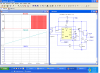
I am attaching a zip file containing both of the designs I am currently working with.
The Fan PWM Control - Best Design_Extra Parts is the one using a 555 and has the Reversing Transistor included.
The Fan PWM Control - Best Design_Final is the one using the 556 and does not use the Reversing Transistor but is currently testing the use of a ULN2003A. (I found one on the Alarm circuit, if it will do the trick.)
Ok, go ahead…. Give me a hard time… I guess since you and Ronv have helped out so much both of you are entitled to knock me around on this…
To clarify, the PWM circuit has been working and I only posted the PWM Circuit on Wed. to see if I may have overlooked something. Ronv kicked back a couple of suggestions and I gave them a try.
However after working with some of the things you guys have been showing me I took a closer look at what I though was working and found my startup circuit was not doing what it was suppose to. (i.e. Start 2 seconds on full power then drop back to whatever the pulse was last set at.)
I mentioned this and Ronv gave me a few additional things to try and I have been working on it every since.
OK! 2 seconds is a long time for a power on reset signal. I spent a long time getting an elegant delay design to work. You didn't buy and J174 Fets did you? I have an idea that should work on power up, but once it has been running all bets are off because the reset time would be long. The 555, in my opinion, is glitchy on power up especially if you want it to "one-shot" type things.
Yes I agree that 2 seconds is definatly over kill, but I wanted to see it work and knew that I could always turn this back with diffrent Resistors and/or Caps...
OK! 2 seconds is a long time for a power on reset signal. I spent a long time getting an elegant delay design to work. You didn't buy and J174 Fets did you? I have an idea that should work on power up, but once it has been running all bets are off because the reset time would be long. The 555, in my opinion, is glitchy on power up especially if you want it to "one-shot" type things.
Sorry, I'm to old to wait for that simulation to finish.
So I ran it in Spice. The only thing I see is that the 10K on the base of the 2N2222 should be between the base and the output of the 555.
Remove the cap on pin 5 and use the 220 Ufd as the power on reset cap (In place of the 47Ufd.) It simulates a ok now. I'm not sure of the condition of the 2N2222, but probably ok.
Unfortunately, haven't learned to simulate things yet. The R1/R2 divider must be greater than Vgs.
It is possible to use lower values for R1/R2 and a high series resistor to the capacitor as well.
The idea is that when power is off, the cap will discharge through J1. A small series resistor to limit the current to about 100 mA could be usefull 12/0.1 or 120 ohms.
When power is first applied,J1 will be shorted (and shorting a pin on the 555) moves it to 100 duty cycle.
R1 charges C1 until it exceeds Vgs, then the JFET opens. The "to power" should be after the power is switched to turn on the motor.
For the power pin use a triangle source. (0 to 12 and back down to 0). A ramp would even be better
At the Top of the JFET, use a LED and resistor to ground. It can sink 100 mA when Vgs is 0V and it woul d have an 85 ohm resistance. Probably could add about 22 ohms in series with the + of the cap.
Try 100K for the top resisr to +12
1 Meg for the resistor across the cap
Make the cap 100 uf.
Before I let too much time get away from me, I wanted to take this opportunity to say “Thank You” to both of you for all the help that you gave me. Without your efforts I would not have been able to complete the circuit using the proper components and/or tolerances… Considering the number of people that appear to visit this website, the two of you were the only ones that took the time to help. Thank You…
I have been testing the circuit from the project board and all appears to be working as intended. If all continues to work well, I will build a PCB from the design in the near future.
Yes I have tested each of the designs using either Transistor Based or LM317 Based Constant Current Regulation circuits. At the moment I am using the SSR Based H-Bridge with the Transistor Based CCR circuit. Although the LM317 appeared to work well, subsequent reading indicates that the LM317 should have a minimum load current of 10ma and I did not know how reliable this would be over time. I would have tried the LM334, but did not have one available. So with that said, I opted to use the Transistor Based CCR circuit.
When I tried the Transistor Based H-Bridge, it appeared as though I was getting different Current values from one side to the other. I switched the various transistor and resistor locations in the bridge, but the difference appeared to follow the condition of the 4001BP. (i.e. Power supplied by on vs. off condition of the 4001BP.) After switching to the SSR Bridge and ULN2003, I discovered that my Multimeter was not providing a true reading based on it’s settings and connections. After making some adjustments with the multimeter, I am now seeing expected readings. I believe that the Transistor Based Bridge would now also provide consistent values from either side, but I have not elected to switch back to prove this yet…
As was indicated early in this thread, Steam Distilled Water has a very high resistance (i.e. Somewhere in the neighborhood of 10M ohms), so it takes a while before I start seeing any type of reading on my multimeters.
Question: When using the Transistor Based CCR, why does the Voltage steadily drops when the mA reading has not reached the adjusted value desired? (i.e. High Resistance requires High Voltage to achieve the same Current Value. Whereas Lower Resistance requires Lower Voltage to achieve the same Current.) So as the resistance starts to drop why doesn’t the Voltage remain High until the current reaches the preset value and then drop accordingly to maintain the desired Current Value.
This site uses cookies to help personalise content, tailor your experience and to keep you logged in if you register.
By continuing to use this site, you are consenting to our use of cookies.

 , as all the parts for this one are already on the Project Board...