Most piezo transducers have a max allowed sine-wave signal of 24V RMS which is 68V peak-to-peak.It is a bridged power amplifier which injects 24V to the transducer.
A bridged car amplifier has an output of 14 watts into 4 ohms which is 21V peak-to-peak. If the amplifier is not bridged then the signal is about 11.2V peak-to-peak into 8 ohms which is only 1.96 Watts RMS at clipping.What are you meaning by 2W out of of a 30W amplifier for an speaker?
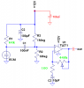
A step-up transformer driven from two small transistors can be used. A power amplifier is not needed since the power to the piezo transmitter transducer is very low.So whats the solution please?
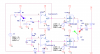
The ratio of the feedback resistor to R10 determines the gain. C2 stops the opamp from amplifying the DC voltage.what are those resistor/capacitor (R10 & C2) in your last circuit that are in series?