Electro Tech is an online community (with over 170,000 members) who enjoy talking about and building electronic circuits, projects and gadgets. To participate you need to register. Registration is free. Click here to register now.
Welcome to our site! Electro Tech is an online community (with over 170,000 members) who enjoy talking about and building electronic circuits, projects and gadgets. To participate you need to register. Registration is free. Click here to register now.
So I have to use a pair of other op-amps to get more gain right?
So I am not able to get more gain just with adding resistors to the before circuit?
Before go to make this circuit you are designed (Thanks a lot for your kind!)
please consider that I need the Offset volatge (I.e the carrier signal) to be amplified too. Does your current modifiction do it too?
Besides why did you notice that you must use a virtual ground BASED UPON opamps?
Why did not you use a pair of resistor dividers?
I Have to take a good view into your current design.
Did you design it so that it just amplify the incoming signal or it amplifies the dc offset to? My goal is to give the 4066 more power by opamps so that I have more power at its output pins.
I guess your current modifiction just amplifies the INPUT signal, not the carrier or DC offset (which creates the carrier or modulation index), Am I right? If so, Please keep in mind that I want to amplify the WHOLE signal (ones which goes into modulator input and consists of both DC offset and the input signal (that's why I tried to increase the gain of those 2 opamps by putting Rf and Rin to them. Make sense?
Sorry for my poor english language
What is your idea about removing the C1 in your last circuit and give the DC offset to the first stage op-amps? Or I am confusing myself by something which seems to be misunderstood?
Yea I see and understand your saying.
Regarding to your first modification:
The formula for the inverting opamp is: (-Rf/Rin)
And for the no inverting opamp is (Rf/Rin +1).
Please correct it if it is wrong.
So you are saying that the opamp has a unity gain for the first circuit right?
Please are you thinking that I will have almost 12V at the output of the modulator some times with the first modification?
What’s your idea about the output current?
Before modify your first modification I used a non iverting opamp at the output of the modulator, So I could improve the output signal. Then I decided to remove this opamp and work on the input of the modulator i.e. the 2 opamps that are used by you to genearet 2 images signals. The result was not satisfied when I simulated it though.
Know please let me know How can I do what I want to do?
Now I do not know what I want. Please direct me before become completely confusing!
I'm not even sure what you are trying to do.
If you want 100% amplitude modulation at the highest carrier level you can get, you need to generate one audio signal that is biased at +9V, and swings 6V p-p. If you invert this (with the second op amp) relative to +6V, which is your virtual ground, you will get an inverted audio signal that is biased at +3V, and also swings 6V p-p. Then you switch between them at the carrier rate. Is this what you want?
Really I want to amplify the output of the modulator, then give it into the input of a power amplifier. It is for an audio from uktrasound device. The output of the modulator is not so powerful so I want to amplify it somehow before injecting it into the amplifier.
(I need a powerful signl for a such device to cause the air to act non linerity..)
Can you tell me how to amplify the output of the modulator before sending it into power amplifier?
Why My non inverting opamp which was connected to the output of the modulator did a such thing for me? I had some distortion so I removed it finally
why did I had ampelification when put an apamp at the output of the opmp?
Ron, Can I amplify the input signal by those 2 opamps which are connected to inputs of the modulator? I want t use a smaller input signal, Or I have to go for your second modification?
why did I had ampelification when put an apamp at the output of the opmp?
Ron, Can I amplify the input signal by those 2 opamps which are connected to inputs of the modulator? I want t use a smaller input signal, Or I have to go for your second modification?
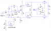
Look at this. I didn't feel like making the schematic "pretty". This is what I simulated.
I don't understand what your "power amplifier" input requirements are. Can you explain?
Look at this. I didn't feel like making the schematic "pretty". This is what I simulated.
I don't understand what your "power amplifier" input requirements are. Can you explain?
So whats the result for this schematic Ron? Can I use it and modify the opamps like your last pic? Did you get a good result from it???
It is a Car Amplifier I removed from a car. It does not have any pre, it is just an 25 to 30W power amplifier. I have no info about it because I am not able to read the values on the chip.
Car amplifiers are 25 Whats to 30 Whats which is only 2 Watts into an 8 ohm speaker. Some car amplifiers use two bridged amplifiers for 14 Watts into a 4 ohm speaker.
You don't have a 4 ohm speaker. You have a high impedance piezo transducer don't you? Then a car amplifier will not make it loud.
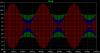
Here are results of simulation of the last circuit I posted, with the audio gain pot set at minimum, half scale, and full scale.
Your car amp probably won't have the bandwidth to handle your carrier frequency.
Car amplifiers are 25 Whats to 30 Whats which is only 2 Watts into an 8 ohm speaker. Some car amplifiers use two bridged amplifiers for 14 Watts into a 4 ohm speaker..
Here are results of simulation of the last circuit I posted, with the audio gain pot set at minimum, half scale, and full scale.
Your car amp probably won't have the bandwidth to handle your carrier frequency.
It is nice circuit regarding to the simulation result. I will try it.
Please tel me know what are those resistor/capacitor (R10 & C2) in your last circuit that are in series?
I tested several amplifiers and this one was the best one. I do not know how can I calculate its bandwidth though?
This site uses cookies to help personalise content, tailor your experience and to keep you logged in if you register.
By continuing to use this site, you are consenting to our use of cookies.