Continue to Site

Welcome to our site!

Electro Tech is an online community (with over 170,000 members) who enjoy talking about and building electronic circuits, projects and gadgets. To participate you need to register. Registration is free. Click here to register now.

  • Welcome to our site! Electro Tech is an online community (with over 170,000 members) who enjoy talking about and building electronic circuits, projects and gadgets. To participate you need to register. Registration is free. Click here to register now.

Repairing a BWD 521 cathode ray Oscilloscope - no traces, hissing noise

Status
Not open for further replies.
Hi again spec.

I've had a look at a few replacement options for the 2N3055, but just wanted to ask your advice as to which on to buy.
If I search for the part number 2N3055, virtually everything I find is a NPN transistor, but the manual clearly states, but it could be wrong of course, given the other errors I've seen in it, that Q42 is a PNP transistor.
The parts list shows it as -60v 1A 30W PNP part number TIP30A

Searching on ebay, if I search for the words 2N3055 and PNP - it only finds 6 sellers, selling 2N3055 NPN paired with MJ2955 PNP transistors.
If I search with NPN instead it finds 62 results, all of which are NPN.

going on a wikepedia search, not always the most reliable source I know, it looks like it certainly is a NPN:
https://en.wikipedia.org/wiki/2N3055

Do you think the manual just got it wrong?

I checked a site I regularly buy components from - rscomponents, again using 2N3055 as the search term, it only finds two NPN transistors.
eg:
https://au.rs-online.com/web/p/bipolar-transistors/5452210/
https://au.rs-online.com/web/p/bipolar-transistors/7743212/

Both are NPN, but have differing specs,
ie,
Maximum Operating Frequency is 2.5MHz for the 2N3055G as opposed to the 2N3055AG, which is 1MHz.
Also, the Maximum Collector Emitter Saturation Voltage is 3Volts and 5 Volts respectively.

BUT, assuming the manual did actually get it wrong, would either of those to transistors be a suitable replacement?

Its all rather confusing I must say.
Speak soon.
Josh

Hi Josh,

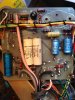
:) You have my sympathies- manuals are very often wrong, sometimes in the most critical areas.

Just to confirm, the power transistor in the inverter is a 2N3055 which is an NPN high power transistor. It is implementing a simple function in your scope so any 2N3055 will be OK, 2n3055H for example.

2N3055 is by far the most widely used high power transistor, and is available cheaply from many manufacturers and suppliers at a very low price.

As, a general rule, it is best to get your electronic components from a reliable source, definately not Ebay. The reason for this is that there a many rip off components on Ebay which do not meet their data sheet specifications. **broken link removed**

The 2N3055 also has a PNP compliment, the MJ2955
https://www.onsemi.com/pub_link/Collateral/2N3055-D.PDF

Some Suppliers:
https://uk.farnell.com/multicomp/2n...crid|78108290589|&CAWELAID=120173390001314700
https://www.cricklewoodelectronics....hJSXvXcg5Mg6n4bwnQyxV4uTFOYY_zeXcYaArBs8P8HAQ
https://www.futurlec.com/Transistors/2N3055pr.shtml
https://uk.rs-online.com/web/p/bipolar-transistors/7743212/

Cheers

spec
 
Last edited:
Thanks spec.
It can be rather frustrating when manuals are wrong....
OK, from what I had read it certainly looked like it was an NPN.
I am going to order a couple from rscomponents AKA re-online.com - although I will be checking them carefully as I had a good read through the link you posted on counterfeit components - and rs components was mentioned once. :(
I normally use them because they are fast - usually overnight, but I think I'll be doing the acetone test on them at least, and perhaps pull one apart and compare to the original if suspicious.

It is amazing what they will counterfeit these days.
They must have access to the same factories the legitimate ones are made, by the look of the product from the outside at least.

I know in my work - I run a small computer repair shop - there are a lot of fake parts.
The worst of them are laptop power supplies - many of the fakes weigh less than half the weight of a genuine.
I think they use small transformers and then overload them up to the "rated" power.

I've had 240v power cables supplied with 240v 3 pin power cables.
If you bend the cable in half, the insulation would split, exposing the narrowest mains cables I have ever seen.
The 3 pin 240v power pins can also be easily bent or snapped of completed with your finger.
Consequently, I don't import them anymore - only tried a few and they aren't worth the risk.
Downright deadly.

iPhone replacement LCD screens and digitizers are flooded with fake components - particularly as Apple don't sell them to non-authorised repairers.
As there are no sources of legitimate supply I have to rely on fakes for them, but I'm upfront and tell the customer.
They are usually happy enough with it, when they compare the price to Apple.
That said though, finding the better quality ones can be a challenge in itself.

Anyway...
I'll gamble on a couple and get back to you soon.
Speak soon.
Josh
 
Hi spec,
I suspect that the 2N3055 is probably OK for the following reasons. I have found that transistors normally fail collector emitter short circuit. (Or if there has been a lot of current available the internal wires melt after they go open circuit after they have first gone short circuit.) As the transistor is hot it can be neither short circuit or open circuit. The current to the inverter will be limited to less than 1.5 amps as it is fed from about 30 volts (+18 and -11.5) via the two 10 ohm resistors R116 and R118. I think either the inverter is not oscillating or is being overloaded by faulty diodes or capacitors on one of its outputs or shorted turns on the high voltage secondary. I think finding out if the inverter is oscillating should be the next step first by trying to measure the AC voltage across the primary using a multimeter on the AC range with a capacitor in series with it. (Or on a DC range with a capacitor followed by a full wave rectifier.) If the ESR of C72 or C73 had increased it could prevent the inverter from oscillating. Another point. I think the 31 and 15 next to the primary windings may be the number of turns rather than the resistance. (The letter may be a T rather than an R)

Les.

Thanks Les,

Good solid info from you as usual.

I agree that the first step should be to check that the inverter is oscillating, but I was a bit worried about the safety aspects.

The 2N3055 is pretty rugged and it is not being asked to do much in the circuit, so like you I don't think it is blown but is simple to check. As you say, they normally blow short circuit C/E due to over temperature when the junctions fuse, but I have seen them, on rare occasions, go to a lowish resistance C/E. Then they do get hot. In this case the 2N3055 is not mounted on a heat sink either.

Thanks for the observation about the turns rather than Ohms- my eyesight is not as good as yours. :) On reflection I would have expected the primary windings to be around zero Ohms.

I am not sure that a few shorted turns on the secondary would give the symptoms displayed. Many shorted turns would though. The other possibility is that the secondary might be open circuit.

Probably like you, I would like to get my hands on the scope to see what is going on.

spec
 
Last edited:
Thanks spec.
It can be rather frustrating when manuals are wrong....
OK, from what I had read it certainly looked like it was an NPN.
I am going to order a couple from rscomponents AKA re-online.com - although I will be checking them carefully as I had a good read through the link you posted on counterfeit components - and rs components was mentioned once. :(
I normally use them because they are fast - usually overnight, but I think I'll be doing the acetone test on them at least, and perhaps pull one apart and compare to the original if suspicious.

It is amazing what they will counterfeit these days.
They must have access to the same factories the legitimate ones are made, by the look of the product from the outside at least.

I know in my work - I run a small computer repair shop - there are a lot of fake parts.
The worst of them are laptop power supplies - many of the fakes weigh less than half the weight of a genuine.
I think they use small transformers and then overload them up to the "rated" power.

I've had 240v power cables supplied with 240v 3 pin power cables.
If you bend the cable in half, the insulation would split, exposing the narrowest mains cables I have ever seen.
The 3 pin 240v power pins can also be easily bent or snapped of completed with your finger.
Consequently, I don't import them anymore - only tried a few and they aren't worth the risk.
Downright deadly.

iPhone replacement LCD screens and digitizers are flooded with fake components - particularly as Apple don't sell them to non-authorised repairers.
As there are no sources of legitimate supply I have to rely on fakes for them, but I'm upfront and tell the customer.
They are usually happy enough with it, when they compare the price to Apple.
That said though, finding the better quality ones can be a challenge in itself.

Anyway...
I'll gamble on a couple and get back to you soon.
Speak soon.
Josh

Hy Josh,

So you are involved in electronics. :cool:

This rip off thing really annoys me. Not so much because of the cost but because it complicates design and development so much, especially with hifi amp design and development. The safety issues you mention sound horrific.

Back to fault finding: what Les says is all good stuff, but I think it is worth checking the three transistors involved with the inverter.

Another check I would do right away is to measure the resistance of all the coils on the transformer, especially the big secondary. I don't think that is the fault, but it is worth a check.

Also, if you feel confident, follow Les' instructions and determin if the inverter is oscillating.

Meanwhile, here is a circuit to test the 2N3055 (22K base resistor). It will also check small signal NPN transistors (100K base resistor), but I expect you can check those with your multimeter.

spec

2016_03_28_Iss01_NPN_TRANSISTOR_TESTER_VER_1.png
 
Last edited:
Hi spec,
I've just downloaded the manual. (Cautiously running Linux Mint from a live CD) Although I can't see how the +150 volt rail effects the inverter it seems to be just the rectified output from a winding on the mains transformer. It might be worth investigating this fault. It looks like after regulation it feeds the deflection amplifiers. If transistors had failed in the deflection amplifiers the trace could be totally off screen. (Just a wild theory.)

Les.
Brilliant Les,

I couldn't get the manual in a clearly readable form and could not establish where the 150V came from.

It would not explain the very hot 2N3055 though, or the lack of EHT crackle on the tube PDA that Josh reported.

There is always the possibility that there are two faults. It is also possible that the 2N3055 is getting hot due to some non catastrophic fault. It might have been getting hot for years.

Intuitively I am suspicious of the germanium transistor, but there is no logic to that.

Also I get the impression that the inverter might not be oscillating.

Cheers

spec
 
Apologies for the delay spec.
OK, just had a read through all the posts and info both you and Les Jones have put up.
Thanks both of you.

I ordered in a replacement 2N3055, and yes, the same symptoms, ie it overheats, and still no traces.
I havent put back the two caps and the diode yet, thought I'd leave them out for a bit in case I need to remove the other two diodes it will make it easier to get to them.
I also checked and it seems like the 2N3055 I ordered are genuine parts. :)
The details printed on it are 22N3055AG BM1512 MEX

So, yes, you were both correct in thinking it is OK, but it was worth a shot.

Re turns - yes, on the printed out manual I have - which is still a pretty bad scanned copy, it does seem to be T for turns.

Sorry if this is a bit of a disjointed post, just trying to go through each post and answer them point by point if possible.

And yes, spec, lol, I guess I am involved in electronics - but to be honest I don't get a chance to work on them that often.
Most of my work is virus removals, software problems, OS installations, data recovery, screen replacements and the like.

The work I do with electronics is usually just replacing dc ports in laptops, moving EEPROMs from faulty hard disk PCBs to donor boards and the occasional replacing diodes and power management chips in laptops.
I also have built a few kits such as an in-system i2c programmer, and circuits for pulse induction metal detectors.

I don't do it enough to consider myself by any means a expert though.

I actually bought the scope to use with the pulse induction metal detector circuit, so I could see the response from the coil and do some adjustments and modifications to the circuit, and for testing different homemake and manufactured coils.
I also thought it'd be handy to use at work on the odd occasion.

I didn't get a chance to use it though, as it lasted only about two days before this issue occurred, and hadn't started using it properly, I was just getting used to it.

OK... back to fault finding....

I honestly wouldnt have a clue how to test if the inverter is oscillating.
I don't have access to another scope, if thats required to test it.

I assume the fact that the replacement 2N3055 behaves identically that I can safely assume the original one is OK and doesn't need testing?

Thanks for the testing circuit, I will pull the other two transistors - Q40 & Q41, and test them asap.
I'll also check the resistance of all the coils while I have the 2N3055 out.
Then I check the diodes as per your suggestion earlier.
It may take a while. :)

Thanks again spec, and thanks also to you Les Jones.
Josh
 
Thought I'd test the transformer first...
Just to be sure I removed the cable you had me test earlier that bypassed C75 and C81.
I still haven't put those components back in yet, as I don't think they'd affect these measurements.

OK.
I measured the resistance from the lower side of R116 to the lower side of R115, as per the schematic, which should be correct to measure the resistance of the 31 turn coil, and it shows no resistance.

I measured the resistance from the right hand side of R117 to the the lower side of R114, to measure the 15 turn coil, and it also shows no resistance.

I measured the resistance from the top of the secondary coil - at the +50 point, to the left hand side of D17 and it measures 641 Ohms.
hmm...

I measured the resistance from the right of R119 to the left of R120, and I get 18 Ohms.
hmm again. ;)

Hopefully the method I used was correct.
Feel free to let me know if that is not the case. :)
Josh
 
A couple of pictures, just in case you wanted to see the actual board...
The transformers a strange looking one.
The large white part, which I guess must be the secondary coil, has two pins coming from it, which measures 641 Ohms.
 

Attachments

  • IMG_2648.JPG
    IMG_2648.JPG
    968.4 KB · Views: 341
  • IMG_2646.JPG
    IMG_2646.JPG
    1.2 MB · Views: 330
  • IMG_2645.JPG
    IMG_2645.JPG
    767.3 KB · Views: 320
And damn!
I think I've found a fault, and it doesn't look good.

There is a crack through the transformer base - or whatever you call the grey unit that the primary and secondary sit on.
I'll take another photo of it.
Sorry I didn't notice it earlier.
Its not visible to the eye under normal lights, I only noticed it when I pushed one of the mounting threads to one side and the gap opened up enough to see it.
Is that a functional part of the transformer - or just a mounting base?
You can guess I'm hoping the later...
 

Attachments

  • IMG_2649.JPG
    IMG_2649.JPG
    1 MB · Views: 339
  • IMG_2651.JPG
    IMG_2651.JPG
    702.6 KB · Views: 340
  • IMG_2652.JPG
    IMG_2652.JPG
    792.3 KB · Views: 319
Consider replacing C80. It looks like it is spilling its insides out.
While you are at it, the other two blue capacitors are probably a bit iffy by now as well.

JimB
 
Hi JimB, and thanks for taking the time to have a look.
I had a close look at C80, and it appears to not be leaking.
The positive side looks a bit iffy in the photos, but I think it is just the reflection in the photo, it doesnt appear to be leaking, but the plastic covering seems a bit discoloured, more from age or heat than anything I guess.
But yes, if I can get it up and running, I'm planning on replacing the caps.
Thanks again.
Josh
 
There is a crack through the transformer base - or whatever you call the grey unit that the primary and secondary sit on.
Yes that is the core, made of ferrite which has a happy knack of breaking sometimes.

I suggest that you dismantle the transformer and stick the broken pieces back together using a cyanoacrylate type glue (superglue), to get as small agap as you can at the repaired break.

JimB
 
Hola Jim,
Could you guess why it broke?
 
I just realised then JimB that it was some type of ferrite.
So it shouldn't be part of the problem then I guess.
I will take your recomendation re gluing it though, once I've worked out the problem.
Thanks again, I appreciate it.
Josh
 
I was thinking that the brown crud by the wire end, indicated by the red arrow, was vomited electrolyte from the cap.

Leaky cap.png

JimB
 
Hola Jim,
Could you guess why it broke?
Hola, Buenos tardes.

I am not sure, but there are a couple of interesting scratch marks on the metal support bar.

JimB
 
You could be right JimB.
I've taken another pic - it doesn't appear to be leaking, it seems like it has/had some sort of plastic film around it that has discoloured.
 

Attachments

  • IMG_2655.JPG
    IMG_2655.JPG
    852.4 KB · Views: 314
OK, that does not look too bad in the new picture.

JimB
 
Status
Not open for further replies.

Latest threads

New Articles From Microcontroller Tips

Back
Top