Continue to Site

Welcome to our site!

Electro Tech is an online community (with over 170,000 members) who enjoy talking about and building electronic circuits, projects and gadgets. To participate you need to register. Registration is free. Click here to register now.

  • Welcome to our site! Electro Tech is an online community (with over 170,000 members) who enjoy talking about and building electronic circuits, projects and gadgets. To participate you need to register. Registration is free. Click here to register now.

Rail gun formulae.

Status
Not open for further replies.

Hero999

Banned
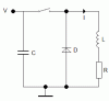
I'm toying with the idea of making a rail gun (just for fun I don't want to kill anyone) but I can't get my head around some of the formulae. Could someone please help me?

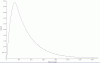
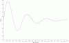
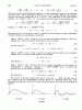
Discharge occurs in two separate phases, the initial discharge which is essentially the first part of a sinewave, then the freewheeling which is an exponential decay as the inductor's feild collapses causing power to be dissipated in D and R.

Firstly are my existing equations correct?

Phase 1:
[latex]f_0 = \frac {1}{2 \pi}{\sqrt{\frac{1}{LC}-\frac{R^2}{L^2}}[/latex]

[latex]v = V sin (\omega t) e^{\frac{-R}{2L}t}[/latex]

Does anyone know how to calculate i or even I?


I've worked out that if R = 0 then:
[latex]I = \sqrt{\frac{CV^2}{L}}[/latex]

However this isn't the case if I introduce R.

If I can calculate I then i should be easy.
[latex]i = I sin(\omega t)e^{\frac{-R}{2L}t}[/latex]

Phase 2:

I understand that this should be the same as the current in an inductor decaying through a resistor, but what about the voltage drop across D?

Please don't point be to a Wikipedia artical on LRC circuits, or differential calculus, because I've read them both and I don't fully understand either. I've touched on this stuff at college but the lecturer was poor and I didn't any point in learning it anyway so I scraped though with the lowest grad for that section and now I'd forgotton what little I knew.:(

However I don't what you to just give me the answer but how to come to the answer and no this isn't coursework.
 

Attachments

  • Diode graph.gif
    Diode graph.gif
    6.4 KB · Views: 750
  • No Diode graph.gif
    No Diode graph.gif
    7.1 KB · Views: 691
  • Coilgun.GIF
    Coilgun.GIF
    2.6 KB · Views: 880
Firstly, your circuit does not make sense. The voltage V is permanently connected across C. So the circuit can't oscillate.

I would have thought that the switch would be a SPDT so that C is connected to V when the sw is in its initial state and when operated, V is disconnected and so C is connected across the LRD circuit.

Thus it would oscillate until voltage decayed to zero and then started to reverse. The diode would then conduct so it would become a L/R decay.

I don't know what the 2 graphs represent. The first appears to be the critically damped case and the second, the underdamped case.

I have not bothered to do the maths. There is no point until you correct your circuit.

Have you simulated it using a circuit simulation software such as Switcher CAD III?

Secondly, there is no point in setting R=0 since, in practice, R will not be zero unless you have a superconducting L & C.

R is the total equivalent series resistance which includes:- the resistance of L, the connecting wires and the ESR of C.
 
Last edited:
ljcox said:
Firstly, your circuit does not make sense. The voltage V is permanently connected across C. So the circuit can't oscillate.
The circuit is a close approximation rather than a true representation.

Imagine the voltage source has a high impedance (which the capacitor charger will be), in fact so high compared to R that it doesn't make much difference.

I would have thought that the switch would be a SPDT so that C is connected to V when the sw is in its initial state and when operated, V is disconnected and so C is connected across the LRD circuit.
That would be a better way of illustrating it.

Thus it would oscillate until voltage decayed to zero and then started to reverse. The diode would then conduct so it would become a L/R decay.
That's exactly what happens, the voltage ocillates, going through the first 90 degrees of a sinewave then decays to vero exponentially, the current does a similar thing, it climbs to a peak in a sinusoidal manner then decays exponentially.

I don't know what the 2 graphs represent. The first appears to be the critically damped case and the second, the underdamped case.
Sorry I should have explained this more clearly.

Graph 1 shows the current in L with the diode present, its grows in a sinusiodal fashion then decays exponentially, it looks critically damped but it isn't.

Graph 2 shows the current in L without the diode, it will oscillate for a few cycles decaying exponentially. This is what I'm having problems calculating, v is not problem but I can't figure out how to calculate i for the life of me.

Have you simulated it using a circuit simulation software such as Switcher CAD III?
I tried in Electronics Workbench, which is what I used to generate the graphs in, perhaps I might try Switcher CAD III.

Secondly, there is no point in setting R=0 since, in practice, R will not be zero unless you have a superconducting L & C.
Lol, I know. I was just saying that I know how to calculate i when R is zero but unless I can do it with R present it isn't much use to me.

R is the total equivalent series resistance which includes:- the resistance of L, the connecting wires and the ESR of C.
I have accounted for the, R is the resistance in the entire circuit.

Thanks for your help.
 
Last edited:
The attached scanned pages from "Electric Circuits" by Joseph A Edminister may help you.

It is the generalised case, so you need to adapt it to your purpose.

Starting at the bottom of page 247 they solve for the current i.

This leads to eq. 47 on page 248.

Note that your eq. for Fo is missing a 2 and the function under the square root is the negative of his.

Now you need to solve for the constants c1 & c2. To do this, I would differentiate eq. 47 and multiply it by L to give you the voltage across the inductor since v = L di/dt.

Then you can find the voltage across the capacitor by adding v + iR. (I expect that it will be -(v + iR) given Kirchoff).

Now you can calculate c1 & c2 by using the initial conditions that Vc = V and i(o) = 0.
 

Attachments

  • p_247.gif
    p_247.gif
    74.6 KB · Views: 996
  • p_248.gif
    p_248.gif
    82.3 KB · Views: 1,912
Last edited:
Thanks for the help. This really isn't simple is it?

Oh well, it looks like I'm going to have to have to teach myself calculus, do you know of any good tutorials?
 
Hero999 said:
Thanks for the help. This really isn't simple is it?

Oh well, it looks like I'm going to have to have to teach myself calculus, do you know of any good tutorials?

It is simple if you know calculus.

I thought you would have learnt calculus in your course.

No I don't know of any tutorials. I still use the books I used as a student if I need to revise something.
 
Even if you know calculus it's not that simple, because the eddy currents in the shot can get pretty complicated. It's the simplest seeming electronics project and ends up being nigh impossible =) Otherwise everyone would have pocket rail guns able to kill at a thousand feet =>
 
Sceadwian said:
Even if you know calculus it's not that simple, because the eddy currents in the shot can get pretty complicated. It's the simplest seeming electronics project and ends up being nigh impossible =) Otherwise everyone would have pocket rail guns able to kill at a thousand feet =>
I was referring to the maths that he is trying to solve, not the project itself.
 
ljcox said:
It is simple if you know calculus.

I thought you would have learnt calculus in your course.
That was years ago and I wasn't very good it it when I did it. :( When I left college I burnt all of my notes, a mistake I'm begining to regret.

Eddy currents aren't that complex, the main factor is the skin effect which isn't that hard to calculate.
 
Hero999 said:
That was years ago and I wasn't very good it it when I did it. :( When I left college I burnt all of my notes, a mistake I'm begining to regret.
All you need to do is to differentiate the current expression that is in the scan I posted.

Remember that if y = a sin (b t) then dy/dt = a b cos (b t),

and if y = a cos (b t) then dy/dt = -a b sin (b t)
 
Thanks but I Googled that and found how out to differentiate.

I asked someone to help me, she found a worked solution in her text book. I think my problem has been that there are many ways to solve this problem. I've been trying to sing from too many hymn sheets, and it's confused me.
 
I haven't got time to show al the working, and I'll just show the relevent parts of the solution. The key is to look at the charge in the capacitor rather than the voltage.

[latex]Q_0 = CV[/latex]

[latex]\alpha = \frac{R}{2L}[/latex]

[latex]\omega_0^2=\frac{1}{LC}[/latex]

[latex]\omega_n=\sqrt{\omega_0^2-\alpha^2}[/latex]

Now for an underdamped system α² < ωo²:

[latex]q=Q_0 \left( \frac{\omega_0}{\omega_N} \right) e^{-\alpha t} sin (\omega_N t+\phi)[/latex]

Where [latex] tan \phi = \frac{\omega_N}{\alpha}[/latex]

[latex]i=Q_0 \left(\frac {\omega_0^2}{\omega_N} \right)e^{-\alpha t}sin(\omega_N t)[/latex]
 
Last edited:
Status
Not open for further replies.

Latest threads

New Articles From Microcontroller Tips

Back
Top