Continue to Site

Welcome to our site!

Electro Tech is an online community (with over 170,000 members) who enjoy talking about and building electronic circuits, projects and gadgets. To participate you need to register. Registration is free. Click here to register now.

  • Welcome to our site! Electro Tech is an online community (with over 170,000 members) who enjoy talking about and building electronic circuits, projects and gadgets. To participate you need to register. Registration is free. Click here to register now.

Questions about biasing an NPN transistor

Status
Not open for further replies.

Heidi

Member
upload_2014-5-29_20-47-25.png

Dear friends,

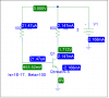
In the figure above, V_BE indicates the Base-Emitter voltage.

In my text, it says "the effect of V_BE “uncertainty” becomes more pronounced at low values of VCC because (VCC - V_BE) determines the base current. Thus, in low-voltage design, the bias is more sensitive to V_BE variations among transistors or with temperature."

I have a few questions about those statements. First, what does it mean by 'the effect of V_BE “uncertainty” becomes more pronounced at low values of VCC?' Is 'V_BE uncertainty' saying that V_BE won't be exactly the same even when transistor Q1 is replaced by another identical one?

Second, I can see that I_B = (VCC - V_BE) / R_B, referring to Figure 5.15 above, once we can be sure about the value V_BE, we know what the base current will be. What does it mean to say "in low-voltage design, the bias is more sensitive to V_BE variations among transistors?"

Thank you!
 
V_be is very temperature dependent. It is not the same for every transistor. It is only approximate. Depending on temperature and current it might be 0.5 or 0.6 or 0.7 or 0.8 volts. If Vcc is 100 volts then the voltage across Rb is 100-(0.7) where 0.7 changes with temperature. In a low voltage, one battery, application the voltage on Rb is 1.5-Vbe. Now the changes in Vbe make a large difference.
 
upload_2014-5-30_15-25-33.png

Thank you, ronsimpson.

I have a numerical test here, I would like to know if it could explain what "in low-voltage design, the bias is more sensitive to Vbe variations among transistors" means.

Assumes that Q1 and Q2 are the same, with parameter Beta=100, but one is driven by 1.5V, another by 3V. I want to see what happens to the collector current Ic if, somehow, the Base-Emitter voltage Vbe increases 1% in each case. Here's the result:
When Vcc=1.5V, then Vbe=766.2mV, Ic=733.8uA. But when Vbe=Vbe*1.01=773.86mV, then Ic=Beta*((1.5-0.77386)/100k)=726.14uA. That is, when Vcc=1.5V, Vbe increases by 1%, Ic decreases about 1%.
In the case where Vcc=3V, then Vbe=794.66mV, Ic=2.20554mA. When Vbe=Vbe*1.01=802.61mV, thne Ic=2.19739mA.
that is, when Vcc is doubled, Vbe increases by 1%, Ic decreases about 0.37%.

So in a lower voltage, the same variation in Vbe results in higher variation in collector current.
Is this kind of analysis correct?

If Vcc is 100 volts then the voltage across Rb is 100-(0.7) where 0.7 changes with temperature. In a low voltage, one battery, application the voltage on Rb is 1.5-Vbe. Now the changes in Vbe make a large difference.
Is 'the changes in Vbe make a large difference' very intuitive? Could you please say more about it because it is not very obvious to me?

Thank you!
 
Last edited:
Hi,

A little math play leads to a closed form solution.

We start with the equation for the base current:
Ib=(Vcc-Vbe)/Rb

We are doing two experiments, one with higher Vcc voltage and one with lower voltage.
We can call the lower or higher Vcc voltage Vcc1, and this allows us to set
the base resistor. For the either voltage we have:
Rb=(Vcc1-Vbe1)/Ib1

The initial current Ib1 and initial base voltage Vbe1 will always be the same, the only thing that changes is Vcc1.

So now we substitute this (and Vcc1) into the first equation and we get:
Ib=(Vcc1-Vbe)/((Vcc1-Vbe1)/Ib1) ...[note Vbe a variable, Vbe1 a constant]

Now the change in collector current is proportional to the change in base current,
so all we have to do is evaluate the change in base current as the Vbe changes.
Taking the first derivative with respect to Vbe we get:
dIb/dVbe=-Ib1/(Vcc1-Vbe1)

or simply:
dIb/dVbe=-Ib1/(Vcc-Vbe1)

Now to look at just the magnitude of the change we can take the absolute value and get:
|dIb/dVbe|=Ib1/(Vcc-Vbe1)

We can now immediately see that Vcc is in the denominator, so as Vcc gets larger the
magnitude of the change in Ib gets smaller. Thus a higher Vcc leads to less of a change
in Ib which leads to less of a change in Ic, which means less change in the bias point.

This is all really just a sensitivity analysis.
 
Last edited:
Heidi,

You have a circuit at 1.5V and 3.0V.
The 1.5V circuit, Vb-e is 1/2 of supply. So any change in Vb-e effects the transistor greatly.
The 3.0V circuit, Vb-e is 1/4 of supply.
If you had a 15V circuit, (1meg and 10k resistors so the current is the same) Vb-e is a small fraction of supply and will have little effect on the transistor.
Make a 1.0V circuit and a 1% change in Vb-e will make a BIG differance.
Try a 0.8V circuit. As you get close to 0.7 volts there will be almost no voltage across R1!
 
Hello MrAl,
We can call the lower or higher Vcc voltage Vcc1, and this allows us to set
the base resistor. For the either voltage we have:
Rb=(Vcc1-Vbe1)/Ib1
Is the purpose here to determine a value of resistance Rb by a certain Vcc1 so that the transistor is operated in its forward active region, and use that constant Rb in the following work?
The initial current Ib1 and initial base voltage Vbe1 will always be the same, the only thing that changes is Vcc1.

So now we substitute this (and Vcc1) into the first equation and we get:
Ib=(Vcc1-Vbe)/((Vcc1-Vbe1)/Ib1) ...[note Vbe a variable, Vbe1 a constant]

Now the change in collector current is proportional to the change in base current,
so all we have to do is evaluate the change in base current as the Vbe changes.
Taking the first derivative with respect to Vbe we get:
dIb/dVbe=-Ib1/(Vcc1-Vbe1)

or simply:
dIb/dVbe=-Ib1/(Vcc-Vbe1)
If Rb is a constant whose value is (Vcc1-Vbe1)/Ib1, where Vcc1, Vbe1 and Ib1 are all constants, I don't understand why dIb/dVbe=-Ib1/(Vcc1-Vbe1) is identical to dIb/dVbe=-Ib1/(Vcc-Vbe1), in which Vcc now is acting as a variable.

Ib=(Vcc1-Vbe)/((Vcc1-Vbe1)/Ib1) ...[note Vbe a variable, Vbe1 a constant]
I guess Ib should be expressed as Ib=(Vcc-Vbe)/((Vcc1-Vbe1)/Ib1), not only Vbe but also Vcc is a variable?
 
Hi Heidi,

Hello MrAl,

Is the purpose here to determine a value of resistance Rb by a certain Vcc1 so that the transistor is operated in its forward active region, and use that constant Rb in the following work?

If Rb is a constant whose value is (Vcc1-Vbe1)/Ib1, where Vcc1, Vbe1 and Ib1 are all constants, I don't understand why dIb/dVbe=-Ib1/(Vcc1-Vbe1) is identical to dIb/dVbe=-Ib1/(Vcc-Vbe1), in which Vcc now is acting as a variable.


I guess Ib should be expressed as Ib=(Vcc-Vbe)/((Vcc1-Vbe1)/Ib1), not only Vbe but also Vcc is a variable?


As you can see, the whole idea is to come up with a formula that clearly and concisely expresses the change in base current with respect to Vcc rather than have to evaluate over and over again the base current with Vcc=5, Vcc=10, Vcc=2, Vcc=999, etc., but Vcc itself is not allowed to change until the very end because it never changes within one single experiment, so that makes it a constant at least until we are done. Once we can express the change we are looking at in a formula that hopefully contains only constants along with the variable of interest, then we can immediately use simple logical deduction to determine the entire behavior.

The main thing though is that Vcc stays a constant to start with, but i thought it would be clearer to express it as Vcc1 to make it more clear that it is a constant rather than a variable, and then later change it to a variable when it was more logical to do so.

What this means is that Vcc=Vcc1 and Vcc1=Vcc. So the only way to express the base current in terms of this is either:
Ib=(Vcc1-Vbe)/((Vcc1-Vbe1)/Ib1)
or
Ib=(Vcc-Vbe)/((Vcc-Vbe1)/Ib1)

and now all we have to do is take the derivative with respect to Vbe.

Does it matter if we use instead:
Ib=(Vcc-Vbe)/((Vcc1-Vbe1)/Ib1)
?

Well, if we take the derivative now with respect to Vbe we get basically the same thing but we end up with what we called a constant in the formula:
dIb/dVbe=-Ib1/(Vcc1-Vbe1)

and so we still end up changing it back later:
dIb/dVbe=-Ib1/(Vcc-Vbe1)

Either way we can now very simply see that when we increase Vcc we decrease the magnitude of the change in Ib.

It's a little confusing because we need the derivative with respect to Vbe, yet later we intend to change Vcc to perform the final evaluation.

It is convenient to be able to remove Rb from the equation so that we have less to think about during the final evaluation.

Also, to double check the final result you can use a numerical derivative.
 
Thank you very much, MrAl, the whole idea is great. I still have one thing that confuses me that I didn't express it very clerly in my last post.

The goal here is that we hope to find relationships among Vcc, Ib, and Vbe under the condition that we keep Rb and Rc constant. So we have 3 variables, and one thing that once Vcc is changed, Ib and Vbe will change accordingly.

When we use Vcc1 (a constant) to find Rb1 (and Rc1, but with a different but similar formula perhaps) by assigning suitable values Ib1 and Vbe1 to Ib and Vbe respectively, Rb1=(Vcc1-Vbe1)/Ib1, with the purpose that the transistor in the circuit is in its forward active mode (B-E forward, B-C reversed biased).

Now if we substitute Rb1 for Rb, but NOT Vcc1 for Vcc, in Ib=(Vcc-Vbe)/Rb, we get
Ib=(Vcc-Vbe)/((Vcc1-Vbe1)/Ib1), a relationship between Ib, Vcc AND Vbe. Not only Ib, but also Vbe varies when Vcc varies.

So when we differentiate Ib with respect to Vbe, and take the absolute value,we get |dIb/dVbe|=Ib1/(Vcc1-Vbe1) or simply 1/Rb1 ( a constant) UNDER THE ASSUMPTION that we hold Vcc as a constant value, but it can be ANY constant. In other words, no matter what value we choose for Vcc, |dIb/dVbe|=Ib1/(Vcc1-Vbe1)=1/Rb1 will not change if I didn't miss something.
 
Hi,

Yes, Rb is not a true constant that is why we try to eliminate it. Rb is a constant within one experiment, but is not constant when we look for a formula that varies with Vcc. Another way of stating this is that Rb is a function of Vcc:
Rb(Vcc1) which then later becomes Rb(Vcc).

Let's look at the setup of a single experiment one time:
1. We start with some collector resistor Rc1, and say we want some output voltage. This requires a certain current in the collector.
2. Due to the Beta, that collector current requires a certain base current Ib1.
3. Due to Ib1 and Vbe1 and Vcc1, we choose a certain Rb that gives us Ib1, call it Rb1.
4. Rb1 gives the right base current for the desired operating point, and then finally we change Vbe to Vbe2 to find the change in base current and that tells us how much the base current has changed with that particular Vcc which we called Vcc1.
So in the above Vcc is a constant, Vbe is not.

Now later, we want to set up another experiment with a different Vcc, call it Vcc2. Now we have to perform steps 1 through 4 all over again because the old base resistor Rb1 is no longer acceptable, so we need Rb2. Now we want to know what happens when we change Vcc without having to go through all the trouble of setting up experiments.

Another way to look at this would be:

Exp1:
Ib1a=(Vcc1-Vbe1a)/Rb1
Ib1b=(Vcc1-Vbe1b)/Rb1

Exp2:
Ib2a=(Vcc2-Vbe1b)/Rb2
Ib2b=(Vcc2-Vbe2b)/Rb2

Note in either experiment only Ib and Vbe change, and in either of these two experiments we want to find:
(Ib1-Ib2)/(Vbe1-Vbe2)

and in BOTH experiments we end up with the same formula except that one contains Vcc1 and the other Vcc2, So we end up with two formulas in a form similar to this:
y1=f(a1)
y2=f(a2)

but in each of these a1 and a2 are always the same physical thing, namely the power supply voltage Vcc, so we can substitute:
y1=f(Vcc)
y2=f(Vcc)

I hope this helps but if not i'll get back here with a full example.
 
Because I want to figure out why the bias in the very top circuit is more sensitive to Vbe among transistors when Vcc is lower, I have considered two equations:
(1) Ib=(Vcc-Vbe)/Rb, and
(2) Ib=(Is/Beta)exp(Vbe/Vt)
(Here I'm only concerned about an NPN in their forward active region.)

To find the bias point of the transistor, I used the first equation as a load line or used the iteration method or simply do this with equation 1:
When Ib=0, then Vbe=Vcc, when Vbe=0, then Ib=Vcc/Rb

In an Ib-Vbe coordinates, equation 2 is a exponential function, equation 1 is a straight line with slope=-(Vcc/Rb)/Vcc. When Vcc is larger, the straight line moves in the up-rhght direction, causing the bias point move upward along the exponential,
which shows that dIb/dVbe is larger at its bias point when Vcc is larger, which leads to a contradiction to what my textbook says.

And I've been thinking "the bias is more sensitive to Vbe among transistors when Vcc is lower", wondering what the author is really trying to say. Does he mean the same type of transistors?

Do you have any suggestions?
 
Last edited:
Hi,

Yes, Rb is not a true constant that is why we try to eliminate it. Rb is a constant within one experiment, but is not constant when we look for a formula that varies with Vcc. Another way of stating this is that Rb is a function of Vcc:
Rb(Vcc1) which then later becomes Rb(Vcc).

Let's look at the setup of a single experiment one time:
1. We start with some collector resistor Rc1, and say we want some output voltage. This requires a certain current in the collector.
2. Due to the Beta, that collector current requires a certain base current Ib1.
3. Due to Ib1 and Vbe1 and Vcc1, we choose a certain Rb that gives us Ib1, call it Rb1.
4. Rb1 gives the right base current for the desired operating point, and then finally we change Vbe to Vbe2 to find the change in base current and that tells us how much the base current has changed with that particular Vcc which we called Vcc1.
So in the above Vcc is a constant, Vbe is not.

Now later, we want to set up another experiment with a different Vcc, call it Vcc2. Now we have to perform steps 1 through 4 all over again because the old base resistor Rb1 is no longer acceptable, so we need Rb2. Now we want to know what happens when we change Vcc without having to go through all the trouble of setting up experiments.

Another way to look at this would be:

Exp1:
Ib1a=(Vcc1-Vbe1a)/Rb1
Ib1b=(Vcc1-Vbe1b)/Rb1

Exp2:
Ib2a=(Vcc2-Vbe1b)/Rb2
Ib2b=(Vcc2-Vbe2b)/Rb2

Note in either experiment only Ib and Vbe change, and in either of these two experiments we want to find:
(Ib1-Ib2)/(Vbe1-Vbe2)

and in BOTH experiments we end up with the same formula except that one contains Vcc1 and the other Vcc2, So we end up with two formulas in a form similar to this:
y1=f(a1)
y2=f(a2)

but in each of these a1 and a2 are always the same physical thing, namely the power supply voltage Vcc, so we can substitute:
y1=f(Vcc)
y2=f(Vcc)

I hope this helps but if not i'll get back here with a full example.
Wow, the experiments seem to be a little complicated to me. But first, I don't understand why we need to change the value of Rb to Rb2 in experiment 2 even when we use another Vcc?
 
Hi again,

"Do you have any suggestions?"

Yes.

This is a little more complicated because we are dealing with two things that change, not just one, so we have to hold some things constant for a time and then later change that.

I should also note that we have to understand the context of this analysis, where we are looking at a certain kind of change for a certain reason. There's no reason why we cant look at other things like other kinds of changes in certain situations, but for this we assume a certain kind of circuit setup where we make some things constant in order to find out the kind of change we are looking for.
For this circuit we hold everything except Vbe constant at first, then later (with a new Vcc) we allow everything except Vbe to change before we allow Vbe to change again, but then it changes by the same amount.
If we did it any other way we would not be finding what we are after, so there is a little context to this problem that has to be observed. For this problem you do it this way, for another problem you do it this other way, etc.
If after more reading you still arent sure what we are doing or why we are doing it you'll just have to ask more questions. I understand this is a little stranger than many other problems that have only one thing change over the entire analysis.

First, you dont have to complicate the analysis by bringing in the exponential form of the transistor or base emitter diode. We can always make the base emitter diode the same and thus eliminate anything else that changes as a result. We can always make Vbe=0.500v and then later change it to 0.505v (a 1 percent increase). We can always do this in any experiment.

The most important aspect of this analysis is the base current. If the base current changes, the bias point changes. But to analyze over two or more different Vcc, we set up any experiment such that it always has the exact same initial base current. The base current is only allowed to change when we change Vbe, not when we change Vcc, because we dont change Vcc yet. The second measurement of the base current will be different for each Vcc that's how we know something is different about the two circuits (two circuits with different Vcc) but the first base current is a set point that will always be the same for any Vcc.

What we are really after here is the "change in the change in base current with Vcc", not just the "change in base current with Vcc".
We ultimately want to know how the bias point changes and that is reflected in the base current change with Vcc, but only after we know how it changes with Vbe. So it's sort of a double derivative. First with Vbe, then with Vcc.

The more simplified and equally valid view is that of biasing a diode alone with a series resistor, looking at how the current changes with Vcc AFTER looking at how it changes with the diode changing voltage. So for each Vcc we calculate the change in diode current, then compare those two currents to find out which one changed the most. The one that changed the most is the worst because that means the bias point changed the most and we dont want that.

Another simplification is that we hold the diode voltage constant instead of making it an exponential. This is valid because we want to know how the change in diode voltage changes the bias current, and so the diode voltage is an independent variable which is not dependent on current (ie we force it to be certain voltages for the tests so we dont need the exponential).

Mathematically if we do two experiments we get two equations:
Ib1a-Ib1b=-(Ib1a*(Vce1b-Vce1a))/(Vce1a-Vcc1)
Ib2a-Ib2b=-(Ib2a*(Vce2b-Vce2a))/(Vce2a-Vcc2)

but because we do the same thing for several things in both experiments these two simplify to:
Ib1a-Ib1b=-(Ib1a*(Vce1b-Vce1a))/(Vce1a-Vcc1)
Ib1a-Ib2b=-(Ib1a*(Vce1b-Vce1a))/(Vce1a-Vcc2)

and now note that we are down to only two things that change, Ib1b changes to Ib2b, and Vcc1 changes to Vcc2, or more toward what we really want the change in base current (on the left of each) changes and the Vcc changes (on the right).
Now it's just a matter of either reducing to one equation by dividing by the change in Vcc, or just calculating each of these to find out which one changes the most.

So first we found the change due to Vbe, then later we found the change in THAT result due to Vcc. This is the more mathematical approach.
Alternately we find how Ib changes with Vbe with a given Vcc, then find how Ib changes with Vbe wth a different Vcc, then compare to see which Vcc caused a bigger change in Ib. This is the more experimental approach and can actually be performed in the lab or in a simulator.

Rb would change for each experiment because we want the same circuit just with a different Vcc, and that means the base current must be the same. Also note that the collector resistor would change too in a real circuit.
 
Last edited:
Alternately we find how Ib changes with Vbe with a given Vcc, then find how Ib changes with Vbe wth a different Vcc, then compare to see which Vcc caused a bigger change in Ib. This is the more experimental approach and can actually be performed in the lab or in a simulator.
Hello, MrAl, thank you very much for your precious time to help me with my weird questions.

I think I need to put the math part off until a later time because it seems to be a little complicated for me right now. Instead, I have done a simulation, but it seems to be showing a contradiction.

Here's what I did:
I use 3 different Vccs: Vcc1=1.5V, Vcc2=3V and Vcc3=6V.
For each Vcc, I plot the Ib-Vbe characteristics by altering Rb from 80k to 100k while keeping Rc not changed.
The result is as shown in the 2nd figure. The horizontal axis is Vbe and the vertical axis is Ib. The left straight line is for Vcc=1.5V, the middle for Vcc=3 and the right for Vcc=6.
upload_2014-6-1_22-48-53.png

upload_2014-6-1_22-51-8.png


For each Vcc, dIb/dVbe is a constant, and is bigger when Vcc is bigger which seems to be showing that at larger Vcc, the change in base current per unit change in Vbe is larger. Doesn't that mean at larger Vcc, the bsae (or collector) current is more sensitive to Vbe?
 
Last edited:
Heidi,
I will say something about this circuit and the two others in post #3. The calculations are all suspect, because the transistors are in saturation. In post #3 you can tell that because the voltages at the base and collector are the same. The base-collector voltage should be reverse biased.

Remember me telling you that the diode curve is highly nonlinear? The current is approximately Is*exp(Vbe/Vt), where Is is the saturation current and Vt=0.026 volts. If the Vbe goes from 0.76620 to 0.79466, the base current will increase by exp(0.79466/0.76620) = 2.821, an increase of almost 3 times.

Ratch
 
Last edited:
I will say something about this circuit and the two others in post #3. The calculations are all suspect, because the transistors are in saturation. In post #3 you can tell that because the voltages at the base and collector are the same. The base-collector voltage should be reverse biased.
Hi, Ratch, thank you very much for mentioning that. I had noticed it a few days ago, and I had changed the collector resistor from 1k to 600 in my later circuit, in post #14, to drive the B-C junction reverse biased.
Remember me telling you that the diode curve is highly nonlinear? The current is approximately Is*exp(Vbe/Vt), where Is is the saturation current and Vt=0.026 volts. If the Vbe goes from 0.76620 to 0.79466, the base current will increase by exp(0.79466/0.76620) = 2.821, an increase of almost 3 times.
Yes, thanks again, I remember. This made me have another question: for the circuit below, how do we calculate the base current?
upload_2014-6-2_9-37-36.png

I've been using Ib=(Vcc-Vbe)/Rb=(3-0.85352)/100k=21.47uA, and that matches the base current in PSpice.

But I believe the base current is also equal* to Ib=(Is/Beta)exp(Vbe/Vt), substituting Is=1E-17, Beta=100,Vt=0.026, we get Ib=0.1807 A=180700 uA! I wonder where I went wrong?

*Ic=Is*exp(Vbe/Vt)
Ib=(1/Beta)Ic, in forward active mode, neglecting the Early effect
 

Attachments

  • upload_2014-6-2_9-33-51.png
    upload_2014-6-2_9-33-51.png
    23.5 KB · Views: 334
Heidi,

Ib=(Is)exp(Vbe/(Vt*N)), where N is a value between 1 and 2. No beta in the Ib equation. In your case, N appears to be 1.1561 .

Why is the emitter current negative? It should be almost the same as the collector current.

Ratch
 
Hello, MrAl, thank you very much for your precious time to help me with my weird questions.

I think I need to put the math part off until a later time because it seems to be a little complicated for me right now. Instead, I have done a simulation, but it seems to be showing a contradiction.

Here's what I did:
I use 3 different Vccs: Vcc1=1.5V, Vcc2=3V and Vcc3=6V.
For each Vcc, I plot the Ib-Vbe characteristics by altering Rb from 80k to 100k while keeping Rc not changed.
The result is as shown in the 2nd figure. The horizontal axis is Vbe and the vertical axis is Ib. The left straight line is for Vcc=1.5V, the middle for Vcc=3 and the right for Vcc=6.
View attachment 86621
View attachment 86622

For each Vcc, dIb/dVbe is a constant, and is bigger when Vcc is bigger which seems to be showing that at larger Vcc, the change in base current per unit change in Vbe is larger. Doesn't that mean at larger Vcc, the bsae (or collector) current is more sensitive to Vbe?


Hello again,

I can see that the problem you are having is you dont have any real context for this analysis so you dont really know what to vary and what to hold constant. The way we do an analysis depends on the context, which means we do it a certain way in order to understand something and that something stems from what we wanted to do in the first place. We can often eliminate certain complexities knowing the context of the problem, and determine what gets varied and what gets held constant. It's very important to know what we are allowed to vary and what we must keep constant, and that comes from the context of the problem. Let me try to give you some context so you can see why we have to change some things and not others.

First though, again, you dont have to bring any exponential forms into this discussion. That's just going to complicate the whole analysis and then take longer to understand. The reason we dont need the exponential form is because we can set the base voltage to whatever we want it to be, we dont have to calculate it from the base current and we also do not need to calculate the base current from knowing the voltage as we can do that in a much simpler way.

Here is the context...
You are given a task to complete, you have to design the bias circuit for a transistor that has a DC current gain of 10, and you have to bias the output to 5 volts, and the circuit should not draw more than about 100ma. You can however choose any Vcc you want from 5v up to 25v, any base resistor, and any collector resistor, but you have to design it such that the bias point change is minimal with any change in Vbe (from temperature or change of physical transistor). What Vcc, what Rb, and what Rc do you use in order to keep the bias point as stable as possible with change in Vbe? The transistor model you are allowed to use is the current controlled current source where the input of the current source is in series with a small battery which represents Vbe and is around 0.5v. Since the gain is 10, that means if you input 1ma into the 'base' you always get 10ma through the collector, just for example.

To make this even simpler though, we are given only two choices:
1. Vcc=10.5v, Rb=2000 ohms, Rc=110 ohms
2. Vcc=20.5v, Rb=4000 ohms, Rc=310 ohms

Which of these two circuits keeps the bias point more constant when Vbe increases by 10 percent, #1 or #2 ?

Note that both circuits provide a 5.000v output with Vbe=0.5 volts.
Also note that with Vbe=0.5v that means in #1 we have 10v across Rb, and in #2 we have 20v across Rb.
 
Thank you very much, Ratch.
Why is the emitter current negative? It should be almost the same as the collector current.
In PSpice, the emitter current reference direction is into the emitter terminal, so there's a negative sign there.

I believe this is also the case in LTspice.
upload_2014-6-2_13-2-34.png
 
Hi again,

In addition to post #18 here is another example.

Same voltages, 10.5v and 20.5v, but this time we hold the base resistor Rb=2000 ohms and collector resistor to 110 ohms, and we want the output biased to approximately 1/2 of Vcc.

With Vcc=10.5v and Vbe=0.5v again, the output is biased to 5v, and when we change Vbe to 0.55v the output goes up by 27.5mv.
With Vcc=20.5v and Vbe=0.5v the output is biased to 9.5v, and when we change Vbe to 0.55v the output again goes up by 27.5mv.
So the fractional percentage change with Vcc=10.5v is 0.0275/5 and with Vcc=20.5v it is 0.0275/9.5. The change with higher Vcc again is less, meaning the bias point (with change of Vbe) is more stable with higher Vcc.
 
Status
Not open for further replies.

Latest threads

Back
Top