Continue to Site

Welcome to our site!

Electro Tech is an online community (with over 170,000 members) who enjoy talking about and building electronic circuits, projects and gadgets. To participate you need to register. Registration is free. Click here to register now.

  • Welcome to our site! Electro Tech is an online community (with over 170,000 members) who enjoy talking about and building electronic circuits, projects and gadgets. To participate you need to register. Registration is free. Click here to register now.

purely reactive load consumes zero average power and reactive power is transferred...

Status
Not open for further replies.

PG1995

Active Member
Hi

The real power P is the average power in watts delivered to a load; it is the only useful power. It is the actual power dissipated by the load. The reactive power Q is a measure of the energy exchange between the source and the reactive part of the load. The unit of Q is the volt-ampere reactive (VAR) to distinguish it from the real power, whose unit is the watt. We know that energy storage elements neither dissipate nor supply power, but exchange power back and forth with the rest of the network. In the same way, the reactive power is being transferred back and forth between the load and the source. It represents a lossless interchange between the load and the source.

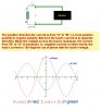
Let's assume we have a purely inductive load, and we have Q=Vrms*Irms*sin(θv − θi). The inductive load will absorb energy in first half cycle and then in the next half cycle retransmits that energy to the source. I hope I have it correct.

Would the electric utility meter give zero reading no matter if the load is run for hours? I assume it will give zero reading. I believe the electric utility meter measures the amount of energy consumed on basis of current passing through it in either direction. Even though the load retransmits the absorbed energy but how does the meter know that? Why would it give zero reading?

In what way the retransmitted energy of the load is used by the source? The source is not some kind of rechargeable battery which will get charged up by absorbing the energy which it previously transferred to the load. If the retransmitted energy of the load cannot be utilized by the source, then that energy has become useless.

I understand that what I say above is a little confusing but I hope you can clearly see my confusion. Please help me with it. Thank you.

Regards
PG
 
Last edited:
Would the electric utility meter give zero reading no matter if the load is run for hours? I assume it will give zero reading. I believe the electric utility meter measures the amount of energy consumed on basis of current passing through it in either direction. Even though the load retransmits the absorbed energy but how does the meter know that? Why would it give zero reading?

My understanding is that an electric meter is designed to estimate real power, and not reactive power. I doubt you will get exactly zero, but presumable the error is small enough to not cost either you or the electric company a significant amount of money. To answer "how the meter knows" is a question of design of the meter, and that depends on the particular meter used. I'll let someone more knowledgable about the details answer that, or you can look up the meter design details.

Also, keep in mind that the electric company would like you to have a power factor relatively close to one anyway because if you have too much reactive loading, you create issues on their side.

In what way the retransmitted energy of the load is used by the source? The source is not some kind of rechargeable battery which will get charged up by absorbing the energy which it previously transferred to the load. If the retransmitted energy of the load cannot be utilized by the source, then that energy has become useless.

As far as "how the source takes back the reactive energy", you would need to know the circuit details to answer definitively. But, generally, the source needs to have a reactive nature to it, just as the load does. A reactive load driven by a non-reactive source just stores energy and does not give it back. The simplest case is a DC source. That would simply charge a cap or a coil.

The simplest case for a source capable of reactive absorption is an LC tank circuit with minimal resistance. The energy just flows back and forth between the coil and the cap. If you think of the cap as the source, then it's easy to visualize how this source absorbs and transmits energy. Of course, you are free to think of the coil as the source too. This arbitrary choice of source versus load maybe will help you understand better. A generator is a bit more complicated, but the same principle applies. You can develop an approximate circuit model of the generator which includes reactive elements.

One thing that adds complexity is the originating source of the energy. A cap with stored charge appears very simple, but that stored energy came from something else. If a battery charged it up, then that's chemical energy, that is real energy transformed. For a generator, the energy source is mechanical. And, the mechanical energy might originate from chemical energy (burning oils) or solar energy (via wind). The mechanical system might have reactive power flow also, since springs and masses are analogous to coils and caps. Presumably, the mechanical reactive power won't recreate chemical bonds or cause fission of helium back to hydrogen in the sun. So, ultimately there is a non-reactive source that starts the process. This is a long-winded way of my saying that the answer depends on the details and often we gloss over the details to keep things simple and focused on the problem at hand.

Often, we make very simple models (even ideal models) for a source. In these cases, you can view the source as a magic box willing to either deliver or accept power, whether it be real or reactive in nature. So, an ideal AC source is assumed to provide real power when current and voltage are in phase. It absorbs real power when they are 180 degrees out of phase. And, the source delivers or absorbs reactive power when they are plus or minus90 degrees out of phase. Any other angles involve both real and reactive power. For ideal sources, the load is completely dictating the flow of power. If this simplicity bothers you, realize that circuit equations are simplifications of electromagnetic field theory, and in a real world problem you could, in principle, calculate the actual field energy flow using Poynting's Theory. Here the reactive and real power flows become more tangible and tractable.
 
Last edited:
Thanks a lot, Steve.

That was an excellent explanation and you have set the discussion on the right track. I do have follow-on queries but I should take some time in order to form a mental picture of what you have already said above.

Best regards
PG

Useful links:
1: **broken link removed**
2: falstad dot com
 
Last edited:
steveB said:
So, and ideal AC source is assumed to provide real power when current and voltage are in phase. It absorbs real power when they are 180 degrees out of phase. And, the source delivers or absorbs reactive power when they are plus or minus90 degrees out of phase. Any other angles involve both real and reactive power.

I think I first need to clarify this. I agree that real power is provided when current and voltage are in phase. But I don't get how real power is absorbed by the source when current and voltage are 180° out of phase. And you say that the source delivers or absorbs reactive power when current and voltage are 90° out of phase. I would have said something like, "the source alternatively delivers and absorbs reactive power", instead. I know it's a minor point but I thought I should confirm it anyhow. Thank you.

Regards
PG
 
Last edited:
Hi,

Power is only absorbed in resistive components. Otherwise it is stored.

The power company meter measures real power, but in any real life system there is always resistance so there is always some power absorbed. If the load in your home is purely reactive (even perfectly reactive) it may still require current from the power line and that means that there will be a voltage drop in the line resistance so there is some power lost anyway. If the load is a perfect LC it may not require any more input, but that's hard to analyze because the LC is not alone it is always connected to the line and the line has it's own impedance to consider.
Ultimately the entire system from power station to load has to be considered.

The theory is such that the power dissipation is zero when the phase angle is 90 degrees, because AC power is calculated from:
P=E*I*cos(TH)
where TH stands for 'theta' and that's the phase angle between current and voltage.

Also from the above we can see that the current and voltage do not need to be in phase they just can not be 90 degrees out of phase for real power to be absorbed.
 
Last edited:
... I don't get how real power is absorbed by the source when current and voltage are 180° out of phase.

OK, my wording here is ambiguous because I'm not clearly defining which current and which voltage. What I mean here is that if the load voltage is in phase with the load current, then the load is resistive and real power is being absorbed by that load and delivered by the source. If somehow the load current was 180 degrees out of phase with the load voltage, then the source would be absorbing the power.

If this clarification is still not adressing your question, then think of the 180 degrees like a minus sign. Normally positive voltage from a source results in negative current through that source. A resistive load has positive voltage drop with positive current flow. If you think of real power as being current times voltage, when they are in phase, then you have negative power for a source and positive power for a resistive load. But, if you reverse the sign on the current (180 deg out of phase), then the load is delivering power and the source is absorbing power.

Yet another way to think about it is to ask what negative resistance means. Negative resistance acts like a source because current and voltage are out of phase, and power is being delivered (not absorbed) by that resistor.


And you say that the source delivers or absorbs reactive power when current and voltage are 90° out of phase. I would have said something like, "the source alternatively delivers and absorbs reactive power", instead. I know it's a minor point but I thought I should confirm it anyhow.

Yes, I like your wording better. Good point.
 
Thank you, MrAl, Steve.

steveB said:
OK, my wording here is ambiguous because I'm not clearly defining which current and which voltage... Yes, I like your wording better. Good point.

This is what I like a lot about persons like you. There are not too many persons who could say this in reply to a person like me. I don't know why some people with scientific knowledge become a god unto themselves. In my view humility and kindness is one of the important traits of a learned and civilized person. When I go though my old threads I discover that in the past there have been many instances when I bugged you and MrAl and some other members a lot but there has not been an instance where especially you or MrAl were rude to me. No flattery intended!

steveB said:
If somehow the load current was 180 degrees out of phase with the load voltage, then the source would be absorbing the power.

I kind of get your point and it seems this text is relevant here. This is what I make out of what you said.

But one thing really confuses me. In an ideal LC tank circuit if there are no resistive losses then the energy will keep on moving back and forth between the cap and inductor once the energy has been injected into the system. Suppose, there is an ac generator whose shaft can be rotated manually and to this generator a purely inductive load is connected. Cutting a long story short, from what you are saying I conclude that the generator can keep on rotating on its own because in one half cycle the generator is supplying power to the load and in the next half cycle the load is supplying power to the generator which makes the generator let rotating without any external input. I understand that what I'm saying is very close to the concept of perpetual motion machine but obviously here we are not discussing perpetual motion. Please help me with it. Thanks.

Regards
PG
 

Attachments

  • power_5.jpg
    power_5.jpg
    597.3 KB · Views: 359
  • souce_absorbing1.jpg
    souce_absorbing1.jpg
    124.6 KB · Views: 349
Last edited:
Thank you for your nice complement. I can't claim to be as good as you say, but I like that your questions are always aimed at true learning that leads to deeper understanding. This is the attitude that I respect very much, and it is the essential quality that I see in all good engineers and scientists of any experience level.

But one thing really confuses me. In an ideal LC tank circuit if there are no resistive losses then the energy will keep on moving back and forth between the cap and inductor once the energy has been injected into the system. Suppose, there is an ac generator whose shaft can be rotated manually and to this generator a purely inductive load is connected. Cutting a long story short, from what you are saying I conclude that the generator can keep on rotating on its own because in one half cycle the generator is supplying power to the load and in the next half cycle the load is supplying power to the generator which makes the generator let rotating without any external input. I understand that what I'm saying is very close to the concept of perpetual motion machine but obviously here we are not discussing perpetual motion.

Essentially you have it correct. But, there are always losses in real engineering systems that we deal with. There is friction on the rotating shaft in the generator. There are resistive losses in the wires that form the coils in the generator, the coil and the circuit connections.

It is interesting to look an modern flywheel based energy storage systems. These are essentially high speed spinning generators with low friction. Some of these use ultra high speed rotation systems in a vacuum with magnetically levitated bearing systems. Now imagine adding superconductors to such a design, such that the generator coils, the load coil and all wired connections have zero resistance. Such a system could drive a coil for a very long time. There would still be some mechanical friction and perhaps some magnetic losses as well. Eventually it will stop, but you can see that what you are saying is correct.

To see a simpler example, just hang a metal ball from fishing line and let it swing like a pendulum. This will swing for a long time. The energy of the ball oscillates between kinetic energy and gravitational potential energy. Air resistance and damping on the line are the real energy losses that will eventually stop the motion, but the energy exchange is reactive, and occurring is plain view.
 
Thank you.

So, let's say we have a load which consumes 15J of real or average power, shuttles 5J of reactive power back and forth, and resistive losses in the wires etc. and friction losses of the system (source plus load) amount to 5J. So, total energy involved is 15+5+5=25J and 20J of energy is spent each second and 5J remains in the system and keep moving back and forth between the load and source. This means the source which could be an ac generator only needs to be fed with 20J of energy each second. If I have it wrong then please let me know. Thanks a lot.

Regards
PG

That's not quite correct, but this is a tricky thing to think about.

As you know, energy and power are different things, even though they are intimately related. The reactive power is basically the flow of stored energy, and the source needs to build up that energy during initial start-up transients. The dissipative real losses (resistance) represents a continuous power loss, while the reactive power flow is not lost.
 
Last edited:
Thank you, Steve.

I need to discuss this topic in detail using a simplified model but we will do it once I'm free. Thanks.

Best wishes
PG
 
Thank you, MrAl, Steve.


This is what I like a lot about persons like you. There are not too many persons who could say this in reply to a person like me. I don't know why some people with scientific knowledge become a god unto themselves. In my view humility and kindness is one of the important traits of a learned and civilized person. When I go though my old threads I discover that in the past there have been many instances when I bugged you and MrAl and some other members a lot but there has not been an instance where especially you or MrAl were rude to me. No flattery intended!


I kind of get your point and it seems this text is relevant here. This is what I make out of what you said.

But one thing really confuses me. In an ideal LC tank circuit if there are no resistive losses then the energy will keep on moving back and forth between the cap and inductor once the energy has been injected into the system. Suppose, there is an ac generator whose shaft can be rotated manually and to this generator a purely inductive load is connected. Cutting a long story short, from what you are saying I conclude that the generator can keep on rotating on its own because in one half cycle the generator is supplying power to the load and in the next half cycle the load is supplying power to the generator which makes the generator let rotating without any external input. I understand that what I'm saying is very close to the concept of perpetual motion machine but obviously here we are not discussing perpetual motion. Please help me with it. Thanks.

Regards
PG


Hi again,


In response to your last paragraph...

You always have to keep in mind that theory and practice are different things, although they work together they are almost always different. But they are often confused together too. When talking about theory sometimes we cant randomly and arbitrarily introduce concepts that are found in practice while still trying to maintain the 'theory'.

For example, i can 'say' that i have a voltage generator with zero source impedance (ideal source), and i can draw it on paper. But like a unicorn, there has never been one ever found in practice. And a common mistake here is to equate the ideal source as being in the circuit, then stating that we should be able to drive any circuit with it like a short circuit. And then someone stands up and proclaims that we can not drive a short circuit with it, mostly because there is not enough energy available in the universe to do that with, but we could drive ANY other load resistance. And then that sounds reasonable.
But is it? What about a load with resistance 1e-1000000000000000000000000000 ohms? Is there enough energy available in the universe to drive that load?

We may not know for sure right now but the point is that when we talk theory like this we have to keep talking theory. We cant say we have a theoretical circuit connected to a practical circuit and ask what happens. Either it is all theory or all practice, we cant mix the two. If we have an ideal source, then it can drive a zero load to an infinite current, period. If we have a non ideal source, then it can not drive the load current higher than what it's series resistance suggests.

What we can do is add elements to the circuit to condition the ideal elements so that they act more as if they were elements that exist in real life. For the ideal source we would add a small series resistance. Then when we connect it to other elements we end up with a circuit that acts like it does in real life.

The other point here is that of the connections themselves. When we examine a single circuit we come out with various results from the analysis. But that analysis is often *restricted* to that one circuit. Once we add elements we often must analyze the whole thing over again because of the interaction of the components.
And this is especially true when we try to combine theoretical models with practical circuits. We end up with one whole *system* rather than a compilation of individual circuits. What happens though is that this new system becomes increasingly complex so we start to look for shortcuts. That leads us to try to understand the system from the individual circuits rather than the system as a whole. This works to some degree, but it usually ends up being just an approximation which does not show us the true nature of the system as well as a complete system analysis does.

So to summarize, when we start with a theoretical model we have to end with a theoretical model, and when we start with a single circuit and analyze it and then add another circuit to that, we have to analyze the system as a whole not as individual circuits in order to ask deeply theoretical questions about the system.
Case in point, when we add something to a turning shaft that was originally assumed to be turning without loss, then it is a theoretical model not a real life shaft so it never 'becomes' a lossy shaft later. An ideal LC circuit oscillates forever with a small pulse input which is then removed. If there is another small pulse later, it adds to the energy in the LC circuit. One way to reduce the energy in the system is to add resistance, and the heat from the resistance has to have a place to go that is considered 'outside' the system otherwise we still havent lost that energy.
 
Last edited:
Status
Not open for further replies.

Latest threads

New Articles From Microcontroller Tips

Back
Top