Continue to Site

Welcome to our site!

Electro Tech is an online community (with over 170,000 members) who enjoy talking about and building electronic circuits, projects and gadgets. To participate you need to register. Registration is free. Click here to register now.

  • Welcome to our site! Electro Tech is an online community (with over 170,000 members) who enjoy talking about and building electronic circuits, projects and gadgets. To participate you need to register. Registration is free. Click here to register now.

Proportional Control Circuit w/ Thermocouple

Status
Not open for further replies.
Well... I agree with ya rolf that the surface area of the tube is greater than that of the element, but here's my thinking..

Lets talk about temperature transfer effectiveness or "influence" on the air.

Say... the surface area of the small tube is 30x the area of the heater.

Per cubic centimeter of area, the element has a much greater influence on the air passing through than the air that contacts the walls of the tube.

I don't know physics. I'm not even the best at math... So I cant write down how it works..

All that I know is, I don't have to really worry about the tube temp.

Why?
#1. Well... first of all... You're hair dryer takes 30 seconds to get to its max temp? Well this thing blows air HOTTER than target within 3 seconds of operation.

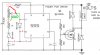
#2 Since it can do that, then all is needed is a simple proportional control to not let it go over during the initial start up and keep it near target.. It is obvious that the element will be working a little harder at the beginning when the tube is at RT to get the target temp... but the power delivered to the element is calculated by the circuit and the target temp is held.

As the tube gets a little warmer with periodic operation, of course the target temp will be reached with less work required by the element, that amount of work again is determined by the controller.

So without really understanding the physics of it... I have witnessed, first hand, that it is totally possible to achieve what I am talking about here.

Ohh and the air flow is produced by a box (computer type) fan.

Volume or air and rate of flow? I have no ****ing clue...

Like I said... physics isn't my thing.... But I am a specialist at ghetto improvisation. :D

I hope you get it working to your liking. Keep us posted, I'll like to hear about your progress, I don't mind being proved wrong, that is part of learning. Much of my physics education is by osmoses because my school learning was mostly forgotten many decades ago.
 
Hi,

I was looking at alternate methods for you to achieve the same result. I though of varying the fan speed as a means of altering the temperature then I stumbled on this.... read it, I think it may work for you.

Thermal Control

by substituting the the fan with an element in the circuit I think you may have your answer.


Cheer
Andrew
 
Lets talk about temperature transfer effectiveness or "influence" on the air.

The word "influence" originally referred to something flowing in from the stars, "flow" being the important thing here.

You may want to get another thermocouple and measure the flow in a different area in the crossflow of the plane of measurement you currently have.

We don't know what your "ceramic tube" is like, but speaking in very general terms about the dynamics of flow in something like this, there's a laminar flow near the ceramic walls thant is slower and influences the airstreams above it. They are all carrying heat, not simply the airstream that happens to lead to your thermistor.

So when the walls of the tube are hotter, the net heat flow through your plane of measurement can increase, even though your reading is (reasonably) constant.

Might explain this, too: "...blows air HOTTER than target within 3 seconds of operation..."
 
Oh - and if you get the SAME readings, make sure the thermistors and thermocouples are not being affected by radiant heat from the glowing element. That's not measuring the temperature of the air. Air is transparent to that IR (mostly, water vapor isn't) and is heated through conduction.

Measuring actual heat flow through a system is tricky, and if you are serious about needing accuracy you need to trace it from source to sink, all the way.
 
You may want to get another thermocouple and measure the flow in a different area in the crossflow of the plane of measurement you currently have.


I'll do that..


there's a laminar flow near the ceramic walls thant is slower and influences the airstreams above it. They are all carrying heat, not simply the airstream that happens to lead to your thermistor.


Interesting.
 
Maybe, but it's going to take a little putzing around. Your thermistor is near the value of the pot: 250k at room temp. The resistance goes DOWN when it heats up, so if you disconnect the leg of the pot that's on the side you turn it to go LOWEST on the pwm, connect the thermistor between the 1k resistor and the wiper on the pot, so it works like that side of the pot... See what I'm getting at? Instead of lowering the resistance with the pot, you now lower it with the thermistor. PWM goes down, heater cools off, thermistor cools off, PWM goes back up, etc.

So I tried this and it did the opposite.... When I disconnected one leg of the pot and connected the thermistor between the 1k resistor and the wiper on the pot, upon operation the PWM signal was very weak and as the element slowly heated up, also heating the thermistor, the PWM signal (power) started to increase.

So... either I am wiring something wrong or maybe I need to try a different approach. I even tried putting adding in the thermistor on the opposite side of the POT an had the same result.

I am a newbie to this stuff so the following paragraph may be hard to understand, but I have a thought that maybe someone can confirm true or untrue.

Can I put the thermistor somewhere in the circuit that controls the "reference voltage?" so that, when cool, the resistance on the thermistor is higher, creating a lower reference voltage, and the result is a higher PWM output; until, the thermistor heats up during the initial initial operation, decreasing its resistance, increasing the reference voltage, reducing the PWM, thereby creating a temperature-dependent reference voltage which I hope can give me the control I need. I also would need some type of tuning POT where the thermistor is to adjust my max PWM output right?

Here's a pic of what I've done so far on the circuit.

#'s 1 and 2 are where I tried splicing in the thermistor (During separate test runs)

Are any of the red question marks in the right location for the thermistor to be a factor in changing the "ref voltage"?


555-jpg.26261
 

Attachments

  • 555.jpg
    555.jpg
    112.8 KB · Views: 538
You had it when you put it where the red line is (make sure you lift the leg on the pot so it isn't in parallel). The potentiomer has to be set toward the low end of the range, and it will get a little sensitive. You might try a 50K pot to make it easier to adjust. This will give the increasing PWM "on" percentage for a decrease in resistance.

When the pot's set at about 50k, at 25˚C it will be about 80% "on". At 140˚C the thermistor is only 4k, and that's less than a 50% duty cycle for the heater. Reducing the value of the pot increases the duty cycle percentage.


Yes, there is a "Control Voltage" on pin 5 - but in this circuit changing that voltage will just change the frequency, not the duty cycle %.
 
Sorry... im just trying to make things clear...

You said lift the leg on the pot so it isn't parallel.


Okay... so reconnect the thermistor loop from the 1K resistor to pin 7 and disconnect the wiper from pin 7

OR

do the same and disconnect the uppermost POT pin?
 
Like this -
 

Attachments

  • therm.GIF
    therm.GIF
    20.5 KB · Views: 181
mmmmkay...

still doing the opposite of what it should.

The power goes up as the thermistor heats up not down like I need it.

Isn't this because where the thermistor is presently hooked up is the PWM output control; where the output is increased, when the voltage @ pin 7 is increased?
 
Last edited:
Hi

When I did my circuit (non PWM) I needed to balance the resistances of fixed resistor to themristor. Granted mine was a comparitor arrangement but the thinking may be the same. The resistance of your thermistor at target temperature is essential to know else you wont get any switching. I started with a 10k thermistor and the circuit would not work at all, changed to a 4k7 and viola.

Check the specs and establish the resistance at 140°C, then make the value of your pot suitable to fine tune as you won't match resistances 100%. At 140°C a 100k thermistor will read about 1k6 ohms. I think you may struggle to get the kind of range you want from the PWM as a 100k thermistor has a swing of ± 600ohms in the 130 to 150°C range.


Cheers
Andrew
 
Last edited:
ohh its switching alright.. just the wrong way..

and the thermistor I have says that its 1,000Ω @ 200°C (231,440Ω @ 25°C), so I think it has less swing in the target area than ± 600ohms

I just need to put the thermistor in a place that increases the power when the Ω's are higher and decreases it when its lower.
 
Hi,

you have a NTC Thermistor, get a suitable a PTC Thermistor that should reverse the operation. If the variable pot is the device that sets the temp then surely the thermistor should be in series with that and the value of the pot reduced to compensate for the thermistor resistance at target temperature?

Cheers
Andrew
 
Well.... thats going to be tough Andrew... I've looked on the net for a PTC thermistor that is as small and fast sensing as the NTCs I have and there's nothing i can find to match it.

The smallest PTCs I have found still have a 10 seconds max in still air thermal constant or whatever. Which is too slow..

There's gotta be some way to put this NTC into the loop.....

I have to figure out where in this circuit I can add this thing in. There has to be a place... its all math right? I just need a reversing factor.

If I can make the NTC Thermistor lower the voltage a little somewhere in the circuit when it is @ room temp, increasing the output power, and vise vesra, will it not work?
 
It's in the right place if you put it where I said to. I took the trouble to build the circuit myself and double-check it on a scope and it behaves just like I said.

Don't know what you're seeing, or why, but if that's really an NTC thermistor (did you measure it?) and you did what I said, it won't be going "the wrong way".

Put a scope on the output of the 555 and look at it.
 
Alright... Progress...

You were right duffy.

It does work now... however I had to reverse pins 1 and 3 of the pot to get it going in the right direction now...

I think how the kit maker layed the pot out on board is different from the schematic.(pins 1 and 3 reversed)

Maybe that explains why, when I turned the POT Clockwise the power was reduced...(Isn't it usually supposed to be the opposite?) and power increased when it was turned CCW.

Anyways.. thats history... the power is high until the thermistor gets some heat... then I can see the element cooling off...

Now I've got some tweaking to do...

Here are a few rough numbers from the bench:

I heated a hot plate to 150 degrees( verified by 2 different thermocouples/meters) and placed the thermistor on the surface with the ohm meter hooked up, waited for it to stabilize and got a reading of about 1,200 ohms.

When it cooled to room temp again it went back up to 255,000 Ohms, so its pretty close to the spec sheet.

*tweaking in progress...*

Whoa... I turned the pot to full power and tried it out and the 1MFD Electrolytic cap started smoking....

and the heating element emits a very high frequency sound when the power is low.

Is this changing the pulse frequency or the duty cycle?
 
Last edited:
After a bit of brainstorming, I had a thought.

What if:

I have a heating element .....

and assuming all calculations are made with a constant volume of air flowing,

if I knew the "effectiveness of heat transfer" of the element, could I not then, create a circuit based on an equation that, with out even knowing the exhaust air temp, calculates the power supplied to the element by knowing the ambient temperature (intake temp) and heating coefficient?


Ex. If I tested heater A @ 25 degrees C., with a fixed air velocity, and the exit temp was 100 degrees C. I could then know the heat transfer coefficient right?


If I base a the power control part of the PWM circuit on an equation that measures ambient temp and knows the heat transfer coefficient of the element (at a fixed velocity) could I not just make a circuit to set the power as X when the ambient temp is Y when the unit is on?

Get what I am saying? Given that all my control factors are tight..(air flow, heat transfer coefficient right, etc..)

That would be in effect mostly open loop control. Control based on assumption of values and characteristic reactions and only using ambient temperature to up date the assumtions. Such is not the why to go grasshopper. ;)

Measure and use the variable that you wish to control, that and only that should be your primary control objective.

Lefty
 
Whoa... I turned the pot to full power and tried it out and the 1MFD Electrolytic cap started smoking....

and the heating element emits a very high frequency sound when the power is low.

Is this changing the pulse frequency or the duty cycle?

That's a power supply cap, sounds like it's too low for your source. Try 100µf. Make sure the voltage rating is at least 16V.

The sound is normal. This circuit changes both the PWM and the frequency. The frequency change won't matter to a resistive load, only the PWM change.


Lefty's right about your open-loop design.

If you are serious about accuracy, it's naive to keep pretending airflow thermodynamics is simple. Look up "Reynolds number" on Wikipedia.
 
Strangely enough, I'm about to build the exact same thing!

Heated nichrome wire coiled in a ceramic ~1/2in i.d. tube, with a small amount of air blown through. I'm even trying for a similar temp. range, of about 120-240C, and have been looking into similar control circuits.

I'm very curious as to how your project is shaping up.

What Thermistor are you looking at? And how am I supposed to use a pot to select a temperature in a linear fashion when a thermistor's response to temperature is non-linear?
 
Status
Not open for further replies.

Latest threads

New Articles From Microcontroller Tips

Back
Top