Continue to Site

Welcome to our site!

Electro Tech is an online community (with over 170,000 members) who enjoy talking about and building electronic circuits, projects and gadgets. To participate you need to register. Registration is free. Click here to register now.

  • Welcome to our site! Electro Tech is an online community (with over 170,000 members) who enjoy talking about and building electronic circuits, projects and gadgets. To participate you need to register. Registration is free. Click here to register now.

Program not working

Status
Not open for further replies.

Cantafford

Member
Hello,

I'm a beginner in assembly language. I have written an .asm code in which I wanted to use a PIC16F876a and a 7 led display to count from 0 to 3.

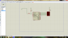
I have uploaded the code in the '7counter.asm' file along with the ISIS schematic that I've used for simulation.

Everything seems ok to me altough when I simulate it I can only see 1 on the 7 segment display, it does not display any other number.

Any help would be much appreciated. Thank you!
 

Attachments

  • 7counter.asm
    1.2 KB · Views: 228
  • schematics.png
    schematics.png
    289.5 KB · Views: 255
Look at your Delay1/2/3 loop, you are looping around so fast ( .6 of a second at 4mhz) you will never see the display changing, before it comes to a halt at the End.
(unless its using a very, very slow clock rate, which the HS_OSC implies its not)

Try using a software delay like below, better still see this tutorial which shows how to use those displays by multiplexing.


Code:
        CALL    DELAY4s

        MOVLW   0x00
        MOVWF    PORTB        ; Set  port LOW
        GOTO    LOOP    


;  SUBROUTINES

DELAY4s                        ; 4 SECOND DELAY at 4 mhz
        movlw    0x23
        movwf    d1
        movlw    0xB9
        movwf    d2
        movlw    0x09
        movwf    d3
Delay_0
        decfsz    d1, f
        goto    dly1
        decfsz    d2, f
dly1    goto    dly2
        decfsz    d3, f
dly2    goto    Delay_0


        return
 
Last edited:
Thanks for answering will check on those tutorials ASAP.

By the way another question. I tried lighting up the segments one by one and here's a really weird thing that's happening. I light up a,b,c no problem but when I try to light up a,b,c,f,g for example no segments will light up...so basically I can only light up 3 segments at one time if I try lighting up more the display will not show anything...that I really don't understand.
 
Again , Nigels tutorial has the answer.

You can see here, that you have to use individual resistors on each of the segments, you cannot put different currents though that single resistor and get the same brightness /voltage in the segments.
 
I have seen some tutorials where no resistors were added in series with the segment pins and it was working. I do not think that is the problem. But I will try to do what you said.
 
I I do not think that is the problem.

Maybe it is not... but what Wp100 says is worth to keep in mind. If by accident, more at this stage of your learning, I your software comes to set a driving pin permanently high, you will have a LED fed with nothing in between to limit the current. Expect some damage to occur.
 
Last edited:
I have seen some tutorials where no resistors were added in series with the segment pins and it was working. I do not think that is the problem. But I will try to do what you said.

No resistors would allow too much current to flow which, in real life, could damage your display, chip, or both. Using a single resistor, however, severely limits the current, so much so that it cannot support lighting up multiple "LEDs" (segments) at a time.
 
I have seen some tutorials where no resistors were added in series with the segment pins and it was working. .

I assume that was a fully working 7 segment program, when it may be possible to go without resistors,because of the high speed multiplexing, but you are really using each segment as individual leds that stay on constantly.

While it may work in Simulation if you try it on actual components without the resistors you run the risk of burning out the i/o port of the pic and /or the led segment.

Have a look at this site which explains how to select and use the right resistors plus other handy output circuits
**broken link removed**
 
Hi Cantafford,
When you say you simulate it do you mean on a software simulator or on physical hardware ? If it is on hardware then check the state of all the port b pins with a multimeter. I would suggest changing the program so that after writing to port B it goes into a loop doing nothing. I you are using a software simulator it may have a display of all the port pin states.

Les.
 
I assume that was a fully working 7 segment program, when it may be possible to go without resistors,because of the high speed multiplexing, but you are really using each segment as individual leds that stay on constantly.

While it may work in Simulation if you try it on actual components without the resistors you run the risk of burning out the i/o port of the pic and /or the led segment.

Have a look at this site which explains how to select and use the right resistors plus other handy output circuits
**broken link removed**
Aight, got it.

Hi Cantafford,
When you say you simulate it do you mean on a software simulator or on physical hardware ? If it is on hardware then check the state of all the port b pins with a multimeter. I would suggest changing the program so that after writing to port B it goes into a loop doing nothing. I you are using a software simulator it may have a display of all the port pin states.

Les.
I was simulating it in proteus virtual simulator not hardware.

Wp100 I have managed to make it work by interconnecting a decoder between the PIC and the 7 segment led display.
 
Your circuit should work if you take advice from the above helpers. Without a resistor on each segment, the display only works when displaying digit "1" as it has the least number of LED to light. digit "0" and "2" will not light as they have more than 2 segments.

I didn't modify your software. It seems OK after I add in the resistor network.

1d 7seg disp.PNG

Allen

p/s I see why it works now. My 876a clock was defaulted to 1 MHz.
 
Last edited:
I use Hi tech C and array for display 7 segment
display [ ] = {0b001100,........}
PORTB=display[x];
 
Status
Not open for further replies.

Latest threads

New Articles From Microcontroller Tips

Back
Top