Continue to Site

Welcome to our site!

Electro Tech is an online community (with over 170,000 members) who enjoy talking about and building electronic circuits, projects and gadgets. To participate you need to register. Registration is free. Click here to register now.

  • Welcome to our site! Electro Tech is an online community (with over 170,000 members) who enjoy talking about and building electronic circuits, projects and gadgets. To participate you need to register. Registration is free. Click here to register now.

Problem with STP16C596

Status
Not open for further replies.

Free_Pcb

New Member
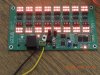
Hi all, the problem i have is this STP16C596 chips get blowns up output pins. I tried everything, searched the whole resources i can get, read the datasheet many times and i have found no problem, the board should work. But when i connect 128 leds to my board, it works for 10 minutes or so then random outpins get blowns up and stays open to ground so the leds attached those pind remain lit. i send my schema please if you could examine it and turn back with advices that saves my life. Thanks
 

Attachments

  • 128Led_103_140705.PDF
    460.2 KB · Views: 247
No idea what the specs on those chips are, but are they supposed to operate without current limiting resistors? - and certainly the power LED isn't - which leads me to suspect you've left all the rest out as well.
 
I connect 60ma white strip leds to the terminals, and there is resistor on the strip led. Those leds on the diagram are for the indication purpose which work with 1.8v. Current resistor for the chip is limiting 80 ma. Thanks for the reply
 
I connect 60ma white strip leds to the terminals, and there is resistor on the strip led. Those leds on the diagram are for the indication purpose which work with 1.8v.

LED's don't work like that - you MUST have current limiting.

Current resistor for the chip is limiting 80 ma. Thanks for the reply

Assuming the chip has internal current limiting, then it shouldn't blow the LED's - but as you're showing all the LED's fed from a 1.8V supply that appears to not be the case.
 
LED's don't work like that - you MUST have current limiting.

i send the photo. those small leds are for indicatiting whether the output pis is ok or not. 8x16 pins on the board are for strip leds to connect thier ground.

Assuming the chip has internal current limiting, then it shouldn't blow the LED's - but as you're showing all the LED's fed from a 1.8V supply that appears to not be the case.
 

Attachments

  • DSCN1541.JPG
    DSCN1541.JPG
    173.8 KB · Views: 1,153
What is Vf of the white LEDs? and what voltage are they connected to? I suspect the power is to high for the chip when they are all on.
 
A 220ohm resistor would program the output-current to 90 or so mA (hard to read the graph,) for a total current of 16*90 = 1.4 Amps
The datasheet says that the maximum ground-current is 1.92 Amps(!), but maybe the chips overheat.

Also: are you really driving all those (8*16*90mA = 11+ Amps) worth of LEDs with a 1.6 Volt supply? A 20-watt supply at that voltage is a rare(ish) beast.
The outputs are current-sources, so you can use anything up to 16 Volts.
 
white leds are driven with 12v. Total of 128 strip leds are connected(6 leds per strip) , each strip consumes 60mA, thus 128*0.06A=7,68 A. 10A 12V switch power supply is connected so power should not be the issue.

Total load per chip is 0.96A which is half load what the chip takes. There are 4 different voltages on the board
12 v for main power which comes from power supply.
3.3 v for bluetooth module.
5 v for cpu chip
1.8 v for red leds which are just indicates the pins activity

white strip leds take 12 v power outside of the board directly from main power supply , strip leds grounds are connected to STP16C596 out pins.

Under full load there is no heat on the chips.
thanks for reply to all
 
I'm still a little confused. :confused:
Usually white leds have a forward drop of about 3.5 volts, so there must be some series parallel combination?
Usually red leds have a forward drop of 1.7 to 2 volts or so. So do the red leds have resistors built in?
I'm not sure it makes any difference - just trying to make sure I understand how it is set up.
I would still try lowering the current (maybe 1/2) and see how long they run.
What do you mean by serial parallel combination? Red leds dont have resistors built in but white strips leds have resistors built in.

Red leds have a forword drop of around 1.5v, and white strip leds have 5v.

Do you recommend put resistors to red leds? Thanks for the reply
 
If there is one white LED in each string, dropping (say) 4 Volts at 80 mA , then the driver will have 8 v/80mA across/through it, giving a power dissipation of 640mW. Sixteen outputs will be over ten watts at peak load. Try lowering the LED supply to ...um: just barely enough to light them?

The monitor LED's should have dropping resistors, because they are driven by voltage.
Your white LED's should not have resistors: they are driven by current.

One last thing: the STPetc datasheet has a mysterious note saying:
Note: 1 To prevent current overshoot, during the Outputs switching, the overhead output voltage must
be less than 1V
2 The Maximum suggested swithing frequency is up to 10KHz
... without ever defining 'overhead output voltage' (or 'swithing' for that matter.)
This might apply here.
 
OK, so this is how I see it now:
The white led has a 25 ohm resistor in series with it to give it a current of 60 ma at 5 volts.
So when you connect it to 12 volts and program the chip for 80 ma the chip has to drop about 6.5 volts.
So now the 25 ohm drops 2 volts, the led 3.5 volts and the chip 6.5 volts for a total of 12.
In this case the chip dissipates .52 watts (6.5X.08) for each led or a total of 8.32 watts for 16 leds.
Per table 5 in the data sheet the junction will rise 75C per watt. Maximum junction temperature is 150C.
Way over.
Your lucky with the red ones. I'm guessing they go out when you plug the white ones in?

You can either add some resistance to the white ones or lower the current so that the power is in spec.
 
Status
Not open for further replies.

Latest threads

Back
Top