Continue to Site

Welcome to our site!

Electro Tech is an online community (with over 170,000 members) who enjoy talking about and building electronic circuits, projects and gadgets. To participate you need to register. Registration is free. Click here to register now.

  • Welcome to our site! Electro Tech is an online community (with over 170,000 members) who enjoy talking about and building electronic circuits, projects and gadgets. To participate you need to register. Registration is free. Click here to register now.

Problem with Class A/AB Odyssey Amp

Status
Not open for further replies.

excetara2

New Member
I am trying to repair this amplifier. Originally when it broke. The positive and negative leads on the speaker terminals were touched together when it was on.

The two fuses inside are blown. Not sure if anything else is wrong. Not sure how to check. The one side is working. The transistors are at like 19Vpp I think. On the other one that is blown it is like 7Vpp or at least a lot less.

Any help on testing to see what is wrong or recommendations for fixing it.

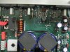
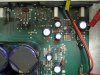
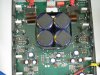
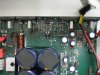
Posting a few pictures below
 

Attachments

  • IMG_0559.JPG
    IMG_0559.JPG
    2.3 MB · Views: 437
  • IMG_0560.JPG
    IMG_0560.JPG
    2.3 MB · Views: 387
  • IMG_0561.JPG
    IMG_0561.JPG
    2.2 MB · Views: 367
  • IMG_0558.JPG
    IMG_0558.JPG
    2.2 MB · Views: 407
Yes, I believe one of the amplifier channels is blown. What is the best way to test what components need replaced.

Jeff
 
Yes, I believe one of the amplifier channels is blown. What is the best way to test what components need replaced.

Jeff

If you have access to an Oscilloscope, a Multimeter, Dummy Load and an Audio Signal generator, you're all set.

At least a Dummy Load and a Meter will be required, you really do not want your precious speakers attached to the outputs until it has been repaired and soak tested, if it puts out DC say goodbye to your speaker coils...

The meter will only really help you to get an idea of voltages in each stage and cold checks on the transistors and resistors etc.

You could build a 1Khz generator with a 555 timer circuit, or an opamp circuit etc, get googlin' a schematic. The dummy load could be fashioned from some high power rated resistors.

A 'scope is really handy for seeing were distortion is occurring or where your signal is disappearing to etc, but unless you're really clever, I would just buy one. You can get cheap USB type 'scopes reasonable nowadays, you don't need much in the way of bandwidth, so pretty much any small traditional 'scope will do you...fleabay is your friend with this.

It might just be cheaper to entrust this repair to a good tech, but then you'll learn nothing more from the experience, other than don't short the outputs!

rgds
 
Yeah, my original problem was shorting the outputs. :(

I am attending school so I have access to all of those. How do I check where the distortion is ocurring. I can see it but what is the best strategy for seeing what's causing it.

THanks,
Jeff
 
Yeah, my original problem was shorting the outputs. :(

I am attending school so I have access to all of those. How do I check where the distortion is ocurring. I can see it but what is the best strategy for seeing what's causing it.

THanks,
Jeff

Well, assuming that it has finished letting out the magic smoke, you use your 'scope to work backwards stage by stage to where you find a signal that is good, at the proper levels and distortion free. Remember you have your sig-gen supplying a 1Khz tone at the proper level to the input and a dummy load on the output.
You can get an idea of what to look for from the working channel, both will be near identical. Then use your meter to measure the voltages to help narrow down the faults in each stage from that point, back towards the output. Repairing each stage as you go. When it's finally back up and running, soak test it for at least 24 hrs before you go plugging in your precious speakers.
Make sure that you run the output for a spell at different volume levels, your intention here is to stress the amplifier as it would be when in use. If it fails again, better it happens on the bench in a controlled environment.

If the problem is still causing the magic smoke to be released, fuses blowing etc, you will need to use your meter to find low resistances, most likely amongst the semiconductors, transistors and diodes etc. Anything you find to have an obvious fault, remove it from the circuit for the time being. Keep doing so until it stops smoking and no longer pops fuses, then fault find with your scope. Don't forget to note what went where, and it's orientation, i.e. what way round it was fitted, so you don't get it wrong when you replace the parts. As you repair each stage, measure your voltages as compared to the other channel, they should be pretty close to each other.
Readings can be compared to the components in the good channel.

This is by no means an exhaustive process, there are loads more things you could do etc, but it will get you most of the way there. A little luck, hopefully, will see you the rest of the way.

I don't need to mention that you need to be very careful whilst working on powered equipment etc, but I will, BE MINDFUL OF LETHAL VOLTAGES.
Oh, and do not short anything with the 'scope or meter probes :)


rgds
 
While signal tracing has it's uses, it's no use whatsoever for a blown DC coupled power amplifier.

First off he needs a circuit diagram, so he can see what he's doing.

Good technique then is to replace ALL transistors in the DC coupled chain, and check the 'obvious' resistors for damage.

The only real test equipment required is a multimeter.
 
Status
Not open for further replies.

Latest threads

New Articles From Microcontroller Tips

Back
Top