Continue to Site

Welcome to our site!

Electro Tech is an online community (with over 170,000 members) who enjoy talking about and building electronic circuits, projects and gadgets. To participate you need to register. Registration is free. Click here to register now.

  • Welcome to our site! Electro Tech is an online community (with over 170,000 members) who enjoy talking about and building electronic circuits, projects and gadgets. To participate you need to register. Registration is free. Click here to register now.

Problem with chained LM3915

Status
Not open for further replies.
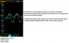
Your circuit is not acting like a peak detector because the transistor is not working. Your 'scope shows that the output of the opamp correctly shows a fast rise but not high enough (It should rise +0.7V higher than the input signal peak) to turn on the base-emitter of the transistor).
Then the transistor is supposed to very quickly charge the output capacitor but yours is very slow, just like the input signal.

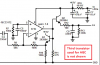
I suspect that the value of R12 is much higher than 100 ohms, maybe it is wrong at 100k ohms? Maybe the opamp and transistor are not powered?

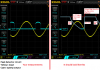
The opamp output high duration is not long enough.
 

Attachments

  • peak detector troubleshooting.png
    peak detector troubleshooting.png
    120.8 KB · Views: 204
  • peak detector troubleshooting2.png
    peak detector troubleshooting2.png
    139 KB · Views: 201
Another problem with the value of R9 and R8 to be so low is that R8 is discharging the output capacitor too soon and too quickly.

My sketch of what the output should look like exaggerates the fall time of the capacitor to be much too fast.
 
opamp and transistor should be powered, collector measured 5v as well as opamp's vcc
R12 is indeed 100 ohms as it should be
R9 & R8 are 100k in that soldered version, are thy still too small?
that sketch you drawed gave much insight what the output should look like
if it matters, i tested bc547 as a basic switch, worked, so at least transistor seems to be OK. and mutlimeter test also confirmed junctions as OK
 
Last edited:
hmm, tested and that gives intended output. But isn't there direct path for negative signals to go into opamps input? i have only single supply in use, i could bias input but then i'd need to get rid of oxcess dc from output....

so at least some version works, but why in earth AG's version won't work, must be simple problem what is overlooked :/
 
Mosaic, your circuit has the signal source driving the input of the opamp below ground (below its negative supply voltage) that is not allowed (it damages the input transistor) for most opamps. The stupid SIM program did not read the datasheet. That is why my opamp is inverting, then its (-) input is never below ground.

Fezder, my actual circuit uses an additional transistor, one for driving the output and the additional one to feed negative feedback. I do not think it will make any difference from using one transistor to do both as you have.
 

Attachments

  • peak detector with two transistors.png
    peak detector with two transistors.png
    86.3 KB · Views: 410
thanks, tested that circuit but same results unfortunately
 
My circuit has worked perfectly and continuously for 9 years and 50 weeks. Yours probably has a wiring error.
 
Oops....my bad.....was sleepy.:eek:

Here it is again.....the MCP6002 handles +/- 300mV compared to its rails. This clamps it to to within 250mV of the rails for normal ops.
peakhold.jpg

EDIT:
Clamping to +/-300mV based on a max 1.2mA peak current thru the BAT54 as per fig1 here:
**broken link removed**

That would require a +/- 12V input signal to achieve due to R1.
 
Last edited:
Hi Mosaic,
With the clamping Schottky diode to ground and when the input signal goes negative then the input capacitor charges that you do not want because its voltage offsets the input away from 0V. It would work better if the input capacitor is removed.
 
Quite so, even clamping the cap with a rev biased Bat54 still permits about a 0.13V increased offset on the peak. Much better w/o the cap.
 
My circuit has worked perfectly and continuously for 9 years and 50 weeks. Yours probably has a wiring error.
i too am thinking this, just have to find that bad contact :) btw, i tested that MCP opamp and it worked perfectly as voltage follower to about 35khz, much better than lm358
 
hehe, found 2n3904's in storage, this is what happens with un-sorted stuff...
circuit now wiht 2904 (correction, 3904, NPN version) , now transistors leads are better seen. Mylars are rated 100v, shouldn't matter?
opamp is still mcp6022, unused half connected as grounded buffer so it won't effect circuit in my understanding
IMG_1064.jpg IMG_1065.jpg IMG_1064-EDITED.jpgIMG_1066.jpg
circuit:
peak detector_audioguru's.PNG
 
Last edited:
A 2N2904 is a very old PNP transistor in a metal can package. It will not work in my circuit. You need a little NPN transistor like a 2n3904. Your breadboard circuit is wired correctly for a 2N3904 but the breadboard contacts might make poor contact.
 
sorry, i typoed that second line it seems, it is 2n3904 (npn) now corrected in post, thanks for noting that.
well i solder this version and we'll see if it makes any difference. This problem is really resilient!
 
i too am thinking this, just have to find that bad contact :) btw, i tested that MCP opamp and it worked perfectly as voltage follower to about 35khz, much better than lm358
MCP OPAs are cost effective once u have low voltage requirements.
 
I did a bit of tweaking to compensate for the cap. charging, The Hi pass input network is a bit different but the results are fairly close. Have a look.
peakhold.jpg
 
here's soldered version with 2n3904, still no good , bugger
otherwise same but reversed vcc/gnd because i mistakenly soldered IC-socket backwards...
 

Attachments

  • IMG_1067.jpg
    IMG_1067.jpg
    161.9 KB · Views: 152
Mosaic, Your new 1.5k value for resistor R7 reduces the DC offset voltage created by the negative clamp diode D1 in the input capacitor C1 to almost nothing. R9 having its low value of only 10k shows the charge and discharge of C4 well but in the circuit its value should be much higher, maybe 100k or 330k.
 
Hmm, guru, i made this circuit and overall it seems to behave better way than those circuits we did before: now output shows peak value.
I calculated cutoff to be about 9.6hz

Sound Level Indicator schematic rev1.PNG
and actual circuit:
Sound Level Indicator schematic rev1-edited.png
output from opamp (transistors bases, i use 2n3904's now that i found them earlier)
yellow output blue input (still not that waveform you linked earlier)
audiogurus-full-circuit-peak output.png
and output from peak detector, input so lm3915's signal pin
audiogurus-full circuit-opampoutput.png

still transistor part won't work as intended, but at least gives peak value now
 
Status
Not open for further replies.

New Articles From Microcontroller Tips

Back
Top