Continue to Site

Welcome to our site!

Electro Tech is an online community (with over 170,000 members) who enjoy talking about and building electronic circuits, projects and gadgets. To participate you need to register. Registration is free. Click here to register now.

  • Welcome to our site! Electro Tech is an online community (with over 170,000 members) who enjoy talking about and building electronic circuits, projects and gadgets. To participate you need to register. Registration is free. Click here to register now.

Problem with chained LM3915

Status
Not open for further replies.
well i suppose it can't hurt....i have only one supply now, so what's best way to add virtual ground (resistor divider or opamp between as buffer? i don't have any ''special'' ic's that create virtual ground....) and i suppose that virtual ground is used as for those groundings in that circuit, but the actual minus from main supply is the one supplied to opamp?
 
The 330nF capacitor will charge very quickly for each cycle then slowly drop its charge in (330n x 330k=) 0.1us which is 100ms to 37% of its maximum charged voltage. One cycle of your 147Hz is 6.8ms so the charge on the capacitor should not drop much for each cycle.
Is your 330nF capacitor 0.33uF or is it wrongly 330pF? What resistance is your 'scope probe? The LM358 is noisy but with a gain of 1 it is not that noisy.
 
The peak detector circuit from the datasheet uses a diode and my circuit uses an emitter-follower transistor as a current-amplified diode. Therefore it is the same circuit as mine except my opamp does not need a negative supply. My circuit charges the capacitor 10 times faster than theirs.
 
capacitor has labeled 334, so isn't that 330n (0.33uf)
well, now that you asked, i don't use those actual probes, just self made which has just pin and banana plug, never thought that would effect in this circuit, as there is no high-frequency involved.
I'll try with proper probe in a few
and input impedance for my scope is 1m/13pf
 
ok, now i use prober probe, impedances are 1/10M, actual resistance is ~240 ohms at 1x setting
 
Most 'scope inputs are 1M or 10M. 240 ohms is a dead short to many circuits including this one.
 
Scope input is indeed 1M, but probe is 240 ohms at 1x setting, 10x is ~10M
 
hmm, i managed to counter that noise, added 10k resistor from that apmlifier stage input to ground, tried before that to add capacitor after amplifier to get rid of DC. (so it works this manner, but still lower bars lit than instant-mode)
any suggestions what would cause so fast decay on peak detectors output? i measured capacitor with meter just to make sure it is 330n
 
The amplifier has a gain of 1 but the 'scope has a gain of 5 for the amplifier output signal.
The amplifier is supposed to have a DC output but your 'scope shows no DC.
The signal input is fuzzy like a hacksaw blade instead of being smooth, maybe the 'scope shows the teeth 5 times larger.
The output has repeating bumps 6 times the input frequency. Maybe they are from the signal generator? Edited

Where did you add the 10k resistor to ground to reduce the noise? The input of the amplifier is where the signal generator feeds. Edited correction. The input of the amplifier is where the output of the peak detector circuit feeds. The input of the amplifier must not have a 10k resistor to ground and must remain a high resistance. The signal generator is supposed to have a low impedance output so a 10k resistor parallel to it will make no difference.
Since the amplifier is a DC amplifier it must not have an output coupling capacitor. With no input signal the output should be 0V or maybe up to 7mV which is the max input offset voltage of an LM358. Maybe your input wire is picking up mains hum? Maybe your IC is fake or is not an LM358? Maybe the output capacitor to ground is electrolytic that stores a phantom charge instead of being a film type?
 
Last edited:
Here is what I see on your 'scope:
 

Attachments

  • peak detector on 'scope.png
    peak detector on 'scope.png
    27.9 KB · Views: 152
The amplifier has a gain of 1 but the 'scope has a gain of 5 for the amplifier output signal.
The amplifier is supposed to have a DC output but your 'scope shows no DC.
The signal input is fuzzy like a hacksaw blade instead of being smooth, maybe the 'scope shows the teeth 5 times larger.
The output has repeating bumps 6 times the input frequency. Maybe they are from the signal generator? Edited

Where did you add the 10k resistor to ground to reduce the noise? The input of the amplifier is where the signal generator feeds. The signal generator is supposed to have a low impedance output so a 10k resistor parallel to it will make no difference.
Since the amplifier is a DC amplifier it must not have an output coupling capacitor. With no input signal the output should be 0V or maybe up to 7mV which is the max input offset voltage of an LM358. Maybe your input wire is picking up mains hum? Maybe your IC is fake or is not an LM358? Maybe the output capacitor to ground is electrolytic that stores a phantom charge instead of being a film type?
thanks for keeping up, i tested only the peak detector just for curiosity how it behaves when i feed it's output to amplifier section,with 10k from amplifier input to ground....only i realized there's only 330k and 10k parallel, so that further increases decay time....so no good obviously
I measured output from generator, nothing more attached, and there wasn't any signal that would look anything like that.
I now have bnc-cables (same what are used with scope) both at scope and generator, at 1x setting (240 ohms resistance)
without signal at all (grounded just to make sure), peak detectors output shows this, could be picking noise as i'm using breadboard, but please judge
NewFile9.jpg
I really can't tell or to be sure whether these lm358's would or not be fakes, of course it is possibility which must be taken in consideration
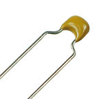
Output capacitor is not electrolytic, it's these, ceramic monolithic, all capacitors i use in this circuit are ceramics, excepct main filter which is electrolytic 100uf
CAPCERMONO_150.jpg

made again measurements, this time from bit more places, ONLY peak detector here,
Blue is input from generator at all these
output from peak
NewFile10.jpg
where 100k resistors meet, non-inverting (+) input
NewFile11.jpg
inverting input
NewFile12.jpg
and, output from opamp, which is connected to bc547 base
NewFile13.jpg

and, dc coupling in both channels
 
and here's pictures from actual breadboard, if i've just made connection error?
IMG_1027.jpg IMG_1027-marked.jpg
 
A breadboard has many rows of contacts with a lot of capacitance between them. It also has many fairly long jumper wires with fairly high capacitance between them and between the many rows of contacts. The rows of contacts and jumper wires are antennas that pickup mains hum, light dimmer hash and all kinds of interference. Use a pcb or compact stripboard layout instead.

A ceramic capacitor is a microphone. Use film capacitors instead for audio or low frequency coupling.

Your 'scope chops up the traces because it is a digital 'scope.
The scope should have a 1M input resistance, not 240 ohms and the peak detector output parts are designed to feed a high resistance input on an LM3915, not a 10k amplifier input resistance.
The opamp has sharp narrow pulses on its output and I do not know why. It might be caused by the very slow speed of an LM358.

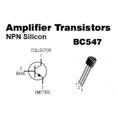
Double-check the layout of the pins (CBE) on the BC547 transistor that are the opposite to an American one (2N3904) that are EBC.
 
hmm, never thought breadboard would cause issues with such ''low'' frequencies, but as you said there are antennas and all that. i'll solder this to vero
A ceramic capacitor is a microphone
now that's new for me! thanks
The scope has 1M resistance (reads all inputs 1M/13 pf 300v rms) and the 240 ohms is from probe hot-tip
I suppose lm358 is not the best opamp to use in here, i'm making order of components, any suggestion for better opamp? something that's not ridicilously pricey....i have feeling you could recommend something more up-to date
well i've checked pinout for bc547, and it should be correctly, colletcor is directly to VCC
b3f2_1-500x500.jpg
 
Tap on a ceramic capacitor or vibrate it with sounds and it produces a signal. Ceramic is similar to piezo material.
Does the 1M 'scope probe have 240 ohms in series with it? Then it will be fine if the peak detector output is not overloaded with a 10k resistor to ground.

There are many opamps that work fine from a single positive supply without needing a negative supply and they are much faster then the slow LM358. I used an MC33172 which might not be available anymore in a through holes package and might be in only a surface mount package now but there are many others.

The peak detector output is supposed to have peak DC voltages that slowly drop when the signal stops. Your scope shows plenty of signal on the peaks which is wrong.

You have shown the correct pins on a datasheet but I cannot see them on your circuit's photo.
 
Tap on a ceramic capacitor or vibrate it with sounds and it produces a signal. Ceramic is similar to piezo material.
too bad i don't have any film caps, might find few if lucky.
Does the 1M 'scope probe have 240 ohms in series with it?
Yes, this is indeed the load now, just checked and there is 1M from scope and 240 ohms from probe in series loading the peak detector, so total is far more than only 240 ohms.
I used an MC33172 which might not be available anymore in a through holes package and might be in only a surface mount package now but there are many others.
I searched around and found ca3130, from what i understood, it works in single supply, slew-rate is faster, 10v/us (closed loop) 30v/us (open loop), compared to lm358's 0.6v/us (unity gain=closed loop?)
input offset voltage is quite close to 358's, 5mv max so not huge improvement there
And it seems ca3130 is rail-rail opamp, and applications say also peak detectors among
https://www.farnell.com/datasheets/31897.pdf

I did check also more up-to-date models from Ti, and there was at least some here, with much smaller input offset (around 250 microvolts or so & single supply) but with smaller slew rate, but, then again, that opamp you use has 2v/us so it could be overkill perhaps to use ca3130 as it has 10v/us.....
I compared mostly input offset and slewrate. And that opamps in question are single supply, rail-rail so no biasing is needed (at least on ground-side) and have at least 5v supply voltage , as lm3915 works well enought in 5v, at least it seemed to work and datasheet confirms it too. correct me if i'm wrong!

oh, and i checked your opamp as for market, there are at least surface mount models, sold around 0.6-1€/piece

and, one thing i really don't understand: what makes what opamp to need dual-supply, and what works well in single-supply? i know it is mentioned or shown in datasheets, but is it in internal-circuit diagram, or in electrical values-table?
 
Last edited:
The CA3130 has a minimum supply of 5V when it barely works. The RCA CA3130 is so old that it needs an external "compensation" capacitor. Almost all opamps except the very old ones have the compensation capacitor built-in.
An opamp can use a single supply if its inputs still work all the way down to its negative supply voltage, then the negative supply voltage can be ground. On a datasheet look at the spec's for "Input Common-mode Voltage Range".

Better more modern opamps are the MC3407x and TLE214x that I have used. The x is 1, 2 or 4 for single, dual or quad in a package. The MC34071 is no longer available in a through holes package.
 
seems i always find old-stuff....
i checked that TLE214x and there are 2-channel versions in TME, 1.5€ (without VAT)/piece, only 22 in stock, deleting this one from catalogue it seems.
before i buy those (which wouldn't be bad idea....) any good way to test these 358's i have, or to use tl071 in that your circuit, even it needs dual supply? i did find also rc4558's, but they need also dual-supply (what i understood) but have better slew, but quite same input offset, but seems to be again oldie....
https://www.ti.com/lit/ds/symlink/rc4558.pdf
 
OK, tested totally different circuit, much simpler and worse but just tested, and at least here it behaves like peak-detector.
blue=input, yellow=output, dc-coupling on both channels. biasing at input so it won't damage opamp, just simple ''super diode'' but solely for testing, i suppose this is sort of waveform we're after at output?
peakie.jpg NewFile14.jpg
 
The datasheet of the TL071 shows that its inputs do not work if they are within 4V from the positive or negative supply. So if the supply is 8V then its inputs cannot go positive and cannot go negative. With a single +9V supply its input can go from 4V to 5V.
Also, the TL071x and TL08x have a fairly common problem called "Opamp Phase Inversion" where the output suddenly goes as high as it can if an input goes closer than 4V from the negative supply. The circuit can be modified to use TL07x opamps with a plus and minus supply.

Farnell (Element 14) in Finland has many TLE214x opamps in stock but the cost for one TLE2141 is 3,04 € and it costs $3.01US over here. Taxes are extra. Use them with a 6V to 9V single positive supply.

Hey! There is white fluffy stuff falling from the sky for the first time this year. Snow. It will be gone in a couple of days when it will be warmer.
 
Status
Not open for further replies.

Latest threads

New Articles From Microcontroller Tips

Back
Top