Electro Tech is an online community (with over 170,000 members) who enjoy talking about and building electronic circuits, projects and gadgets. To participate you need to register. Registration is free. Click here to register now.
Welcome to our site! Electro Tech is an online community (with over 170,000 members) who enjoy talking about and building electronic circuits, projects and gadgets. To participate you need to register. Registration is free. Click here to register now.
This may be slightly OT.
How about an LM3915 that shows the peak AND the instantaneous simultaneously?
This would require multiplexing the input with an appropriate clock.
Perhaps a 555 timer (@ 60Hz) driving an output transistor to create a bistable switching voltage rail ( output Tr collector V and actual 555 pin 3 output V) which then drives the collectors of a pair of emitter followers (one base fed by peak hold and the other by instant audio signal) with joined emitters to feed the LM3915 input.
The 555 duty cycle can be adjusted to alter the relative brightness of the peak and instant LEDs.
The original AC input signal could be DC biased with a + 0.6V to offset the e-follower PN junction drop.
Your amplifier is rated to produce 100W at low distortion but only when one of its 6 outputs is playing which is odd. The spec's do not say how much the output power drops when more than one channel is playing.
The peak detector will be destroyed if the signal is higher than it is designed for.
We hear peak levels which can be up to 10 times the voltage of average levels. Peak detected signals will cause the LEDs to be bright. You will not see fast instantaneous signals and fairly fast instantaneous signals will appear to be dimmed.
Perhaps from the POV of visual interest in the display, there could be two RC networks. One for sustained peak detection and a second, faster RC network that more accurately tracks the transients but keeps them visible.
Your amplifier is rated to produce 100W at low distortion but only when one of its 6 outputs is playing which is odd. The spec's do not say how much the output power drops when more than one channel is playing.
well, when i bought this amplfier many years ago, i did't pay attention to stuff like this, was just looking for ''all-round'' 5.1 amplfier which has plenty I/O's, wattage didn't matter much as i don't listen music loud.
If you listen to music with the volume turned down so the average power is 1W then peaks can be as high as 14W without sounding too loud. 2W is only a small increase in volume, maybe you are actually averaging 5W then peaks can be as high as 70W.
Your amplifier can produce a very high output signal. It is difficult to limit the input signal to the peak detector when the supply is a single positive supply, with a dual polarity supply it is easier to limit the input. I was thinking about adding a biased opamp follower to the input of the peak detector and use diodes to limit its input swing to almost the supply voltage of a single positive supply but sorry, I am too busy to doo dat.
An instantaneous detector will not show fast clicks or beeps because their duration is too short (less than 30ms) for our vision. A peak detector will stretch the duration of every click or beeps long enough to be clearly seen.
well i measured around 10mv from speaker volume down, still on of course, but my meter doesn't have true-RMS or any of that fancier stuff, should look with scope to get better value.....i sometimes forget that i lack DMM that has RMS or similar, but it has at least data hold (rish multi 14, found from local auction site for 20 euros)
I was thinking about adding a biased opamp follower to the input of the peak detector and use diodes to limit its input swing to almost the supply voltage of a single positive supply but sorry, I am too busy to doo dat.
Most multimeters measure only 50Hz and 60Hz accurately. Sometimes only your sub-woofer plays those frequencies. Other channels on your 5.1 amplifier produce those frequencies at very low levels (10mV).
My "VU bar graph" does not connect to my amplifier because its input is a microphone. It displays the loudness of the TV, the stereo and talking. It has been displaying continuously for 10 years.
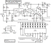
I added some parts to trick the LM3915 into two bands of levels, very sensitive and fairly loud. Then instead of 30dB with one LM3915 its range is 50dB. Here is its schematic:
Most multimeters measure only 50Hz and 60Hz accurately. Sometimes only your sub-woofer plays those frequencies. Other channels on your 5.1 amplifier produce those frequencies at very low levels (10mV).
ew, thought so....time for scoping. I do have subwoofer, bought it just because my speakers didn't output enought bass for my liking, even they are car speakers in custom made boxes, 6x9'' 4 way, sony xplod, only they were bought used and it sounds like coil or something is hitting something (not bottoming thought) at left front channel. Haven't seen anything that would cause that noise during bass-based music, but i'm planning to buy new pair, probadly similar because sound is good so makes buying easier with these specs (unless these specs are false of course....)
Bit off-topic there perhaps
ah, clever. That was in my mind too but have absolutely no clue what sort of microphones do their job for such application, and the there's placing ''problem'' too
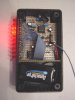
is that veroboard in that enclosure double sided? nice build & schematic!
i do understand that peak-detector section somewhat, but, what function is with those q1 & q3? and i suppose for mic-amp section, non-inverting output has dc-offset made with those 100k & 47k resistors. C1 is at lest so dc won't go from power rails to that non-inverting output yes?
Just trying understand topology in that circuit, i see less point using circuit unless knowing what's happening there...
They cannot spec how a speaker will sound and they lie a lot anyway.
That was in my mind too but have absolutely no clue what sort of microphones do their job for such application, and the there's placing ''problem'' too
Thanks. It is a copy of single-sided Veroboard made in China. The copper strips form half of a pcb and the parts and a few short jumper wires form the other half.
understand that peak-detector section somewhat, but, what function is with those Q1 & Q3?
Opamp IC1b has a low output current so it drives Q2 that can apply a lot of current to quickly charge peak holding capacitor C8 but allow R13 to discharge it slower. Q1 has the same Vbe voltage drop as Q2 and applies negative feedback to the opamp. Q3 quickly charges capacitor C9 then it discharges very slowly (about 2.5 seconds) into the resistor ladder in the LM3915. The voltage on C9 feeds Rhi of the resistor ladder but resistor R15 biases C9 at about 0.56V when sound levels are low so the circuit is very sensitive. Loud sounds cause Q3 to charge C9 to 10 times the 0.56V idle voltage that reduces the sensitivity 20dB.
Suppose for mic-amp section, non-inverting output has dc-offset made with those 100k & 47k resistors. C1 is at lest so dc won't go from power rails to that non-inverting output yes?
IC1a is a standard opamp biased at half the supply voltage. The two 100k resistors in series from +5V to ground make 2.5V. The 2.5V is fed through the 47k resistor R4 to the (+) input of the opamp so that its input and output can swing up and down.
C1 blocks the DC voltage that powers the electret mic from affecting the 2.5VDC at the input of the opamp.
I too mostly prefer analog meters, give better overall perspective on things, like car rpm meter and such. But, it's good to test around and play with different crcuits
Yes, this i was too wondering last night, as they have such ''strange'' resistor ladders inside, logaritmic scale won't be logaritmic when they are just chained together.
Oh, just recalled one embarassing thing, i still have that oscilloscope, remember that one which we shot with freezer-spray? I totally forgot that, suppose i could start redoing something with it, only i'm not sure about ''necroing'' thread, but then again, it was confusing thread
When the logarithmic LM3915 ICs are chained then the lowest level one needs its sensitivity increased (or the highest level one needs its sensitivity decreased) 30dB. You might as well use an opamp to increase the signal to the lowest level one to avoid input offset voltage problems with very low levels.
that is current circuit in use, along with peak-detector of yours (peak-detector is BEFORE 30dB amplifier) ordered 3 colours of rectangular led's, should arrive by monday. i need those rectangular ones anyway in some other projects in future
edit: well actually circuit is that both sections have same full-scale but other is fed viad amplfier section and other is non-amplfied
This site uses cookies to help personalise content, tailor your experience and to keep you logged in if you register.
By continuing to use this site, you are consenting to our use of cookies.
")