Continue to Site

Welcome to our site!

Electro Tech is an online community (with over 170,000 members) who enjoy talking about and building electronic circuits, projects and gadgets. To participate you need to register. Registration is free. Click here to register now.

  • Welcome to our site! Electro Tech is an online community (with over 170,000 members) who enjoy talking about and building electronic circuits, projects and gadgets. To participate you need to register. Registration is free. Click here to register now.

Problem with chained LM3915

Status
Not open for further replies.

fezder

Well-Known Member
Right, so i took audiogurus advice earlier and bought LM3915 (or was is 16 suggested? won't matter much i suppose.....)
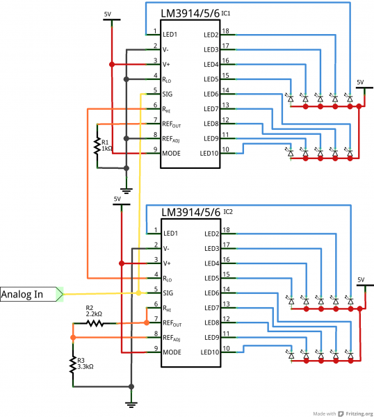
Now, with one, works as intended, at first leds light easily then harder. Troubles began when i placed two in following circuit:
the example on page 14 (opamp version) works as intended.
The problem is, the first 10 leds work well in log. manner, BUT the next one, it works like first one, i mean first leds light EVEN easier than first on first 10 leds, Shouldn't those first leds light up on second bar harder than previous bar's last ones, like if they'd continue working on 3db ladders?
capacitors i have as follows:
2.2uf from led's anodes to ground (both bars)
0.1uf accross r3
100uf at power bus
tried changing ic's in case faulty is in game.
for testing i use now potentiometer to supply analog signal (voltage divider) to signal input
And, supply voltage is 12v, even for led's
Probadly this is another some foolish error i've made in circuit....
lm3915_1.jpg lm3915_2.jpg

52d71728ce395f7c5c8b456f.png
 
The ladder voltages for the two 3915s may not be right. Try the circuit in Fig 21 or 22 of the Texas Instrument datasheet for the 3915.
 
Hey alec, i tried that picture 22 earlier today, it works much better, but, i didn't try that non-opamp version at all, worth shot. The reason why i didn't try it was due the possible noise-problems, but i try it
thanks!
 
Right, so i took audiogurus advice earlier and bought LM3915 (or was is 16 suggested? won't matter much i suppose.....)
..............................
Well it does, depending upon whether you want a linear response or a logarithmic (VU) response between the input voltage amplitude and the number of lit LEDs.
 
lm3914=linear
lm3915=log.
lm3916=VU, log in it's own way?
well at least there is no 14 in here circuit, problem would make sense then hehe

right then, i tried that circuit picture 21 in datasheet (page 14) but now another strange problem occured.
in bar graph setting, first bar shows as dot, that disappears sometimes so there seems to be some sort of oscillation somewhere....but, that next section behaves NOW normally, but nowhere near that symptom what that first circuit i posted has
 
sorry, i take that last back, i had placed ONE lead to wrong place: r2 was right at ic1 pin7, instead of 8, oops.....well nothing burned, main thing...
now just need to figure out how to substitude calculations to this circuit, i mean led current and vref's
 
About 35 years ago I built a 60dB display using two LM3915 ICs and it still works perfectly. In those days they made modules with the IC already mounted on a pcb complete with a bar or 10 LEDs.
I use LM3914 ICs to display linear voltages, LM3915 to display audio levels but I have never seen an LM3916 because its LED level thresholds are all over the place.

The datasheet has a simple formula and graph showing Vref and LED currents.
 
LM3916 because its LED level thresholds are all over the place
hmm, good to know!

about those formulas when using image 21 circuit, are potentiometer/trimmer treated with added value from resistor before it? i mean resistor before it at shematic like r1+r2=r2 and r3=r1 for voltage ref formula? sorry if i asked in strange way, but i get around 1.5 volts when using formula with those values for first section of leds, but for second bar, vref is ~9.6volts, much closer for 10v full scale.
But, datasheet says that vref for first bar is 360mv, 0.36v, so how is that calculated? i see that ref adj pin is set different place in each of those sections, but, how is that first section calculated?

edit: and RHI nis also differently in both those, seems to affect formula
 
But, datasheet says that vref for first bar is 360mv, 0.36v, so how is that calculated?
Voltage across R3 = 1.25. Vref = voltage across (R1+R2) ≈ 1.25*(260/1k) ≈ 0.325 if we neglect 80uA from the Radj pin and assume the trimmer (R1) is at mid-position.
 
Voltage across R3 = 1.25.
due internal reference? well, that formula was much easier than i thought, thanks!
any specific reason why RHI is differently in both sections? just trying to understand a much as i can from this new ic for me
and one more question, how led current is calulated in that first section?
edit: by different i mean placed in different place
edit2: found info abou led current, missed this one on page 8, current programming....
 
Last edited:
Use two LM3915 ICs and the "60dB Dot Mode Display" circuit that uses an opamp. The opamp amplifies the levels for the low signal LM3915 by 30dB so that its input offset voltages do not mess up the accuracy and it makes the circuit much simpler.
With the low signals amplified 30dB then the voltage on RHI is the same for both ICs. The LM307 opamp shown is very old and any opamp can be used but a low noise audio opamp is best. Most opamps in that circuit need a positive and negative supply.

You should use a peak detector circuit. The datasheet shows some of them.
 
faceplate-demo.png
Hi, I built something similar back in 2k9 as a 20 LED turbo gauge. The trick was to calibrate the 'start' voltage of the 2nd LM391x to be > than that of the 1st LM391x end voltage. By using the 'end cal V of the 1st LM391x as the 'start' cal V of the 2nd..it works well, I called that the 'mid-cal'.
Here are a few pics that might help. Note the calibration pots & text. Sorry for the haywire layout...Q&D job. Works well though! There's an associated logic board that connects to this one to handle the trip points and the lean/rich display, but that doesn't relate directly to the pressure gauge here. There are a couple extras like a dimmer when the car's lights are switched on and a switch to change the 'range' of the calibration to work for different max PSI boost. Also some front end Vcc TVS limiting for 'load dump' protections as per the ISO spec. req. for automotive electronic sub assemblies.

If u lookk you will see a POT-LO, a POT-Mid and a POT Hi for calibration...the Lo and Mid governs the 1st 10 LEDs and the Mid to Hi governs the next 10 LEDs.
There's a 10K trim pot that's used in conjunction with the 'range' switch to ensure the gauge can switch from 30 PSi to 15Psi as required.

Eaglesch.jpg

eacgle-pcb.jpg

Edit: it was built and fitted into a ....Tuna Can, powder coated for good effect!
If the OP uses EagleCAD I can post the actual schematic and PCB layout.
 
Last edited:
Fezder is making an audio color organ so it needs logarithmic LM3915 ICs, not linear (for a voltmeter) LM3914 ICs.
 
any bit help and information is greatly appreciated!

about peak-detector, i suppose it's best placed after amplifier section? and, only op amps i have currently IIRC are lm358 and tlo71, and quad versions of those. Preferably i'd use single-supply circuit, but i don't understand what causes each circuit to need dual supply and what works in single supply?

Also, it seems that opamps don't like negative voltage applied (too much) to inputs, but they're mostly according to datasheets around 0.3v, and i'm planning to build 1w for 4ohm speakers (2 volts full-scale, correct?) and then smallest detection is ~1.9mv, -60db from 2 volts. sure, i could make 1 watt -30dB, but i don't listen that loud, my amplifier puts in ''idle'' (volume just on from amplifier, full volume from computer) around 10mv.
It seems to work well without opamp peak-detector, i calculated values as:
first section
r3=1k
r2= 47r
r1=47r

led current is ~10ma, ic is bit hot so i'll switch values for lower current

and for second section, upper scale
r6 = 1.2k
r5 = 680r
r4= 100k trimmer ( didn't have breadboard friendly trimmer, so had to use that one....)
 
You can use single supply OPA but u need to Bias them to ensure your output signal doesn't get clipped. Also the lm358/324 series have Class A crossover distortion at the middle of the supply rail , so you'll have to force class B operation to get a cleaner signal.
The Tlo71 is best used with a dual supply I believe as they are far from rail to rail units.
Since this is a peak detector build, have you considered discrete transistors? Using them builds stronger fundamentals in electronics.
Perhaps you can invest 12 minutes here:

I'd suggest a common emitter amplifier (A.C. gain enhanced by a capacitor across the emitter resistor, and neg. feedback gain control) followed by a common collector (emitter follower) impedance buffer for your peak detector with an RC combo to govern the peak decay.
 
Thanks for info Mosaic, i watched that video (wasted 12 minutes, baa....kidding) and it was infomative.
I do have transistors, dunno for where these are good but i suppose 0.5w versions are good enought for small power amplfication and/or peak detector
bc547 & 557
a1015 & c1815
2n5551 & 2n5401
all should be complenetary npn/pnp pairs, if that makes any difference or helps in any way, but i suppose we're not designing push-pull things here
But, even with peak detector, we still use lm3915, right?
 
about peak-detector, i suppose it's best placed after amplifier section?
Yes, the peak detector feeds the two LM3915 bar graph ICs. The peak detector is important because our vision cannot see fast peaks that occur in music and speech. The peak detector holds the voltage of each peak for more than 30ms so we can see them all.

and, only op amps i have currently IIRC are lm358 and tlo71, and quad versions of those. Preferably i'd use single-supply circuit, but i don't understand what causes each circuit to need dual supply and what works in single supply?
The LM358 is an old low power opamp so it is slow, noisy and has crossover distortion. But its inputs can work fine all the way down to 0V when there is a single positive supply so it does not need a dual polarity supply.
The TL071 is fast, low noise and has extremely low distortion so it is used for audio. But its inputs do not work within 4V from its negative supply voltage so with a single positive supply its inputs should be biased at about half the supply voltage so that they do not go within 4V of ground. But the LM3915 ICs do not work properly if the opamp is biased and do not need a negative supply so use the LM358 opamp instead, you might not notice its noise on the bar graph.

Also, it seems that opamps don't like negative voltage applied (too much) to inputs, but they're mostly according to datasheets around 0.3v, and i'm planning to build 1w for 4ohm speakers (2 volts full-scale, correct?) and then smallest detection is ~1.9mv, -60db from 2 volts. sure, i could make 1 watt -30dB, but i don't listen that loud.
My peak detector will work fine with an opamp in an LM358 or LM324 and is inverting so its input never sees a negative voltage if the input signal is not too high.
1w into 4 ohms is a signal that is 2V RMS which is 2.828V peak. 2.828V peak into 4 ohms causes a current of 2.828V/4 ohms= 707mA which is much too high for a BC547 and BV557 which perform poorly above only 60ma and are destroyed above 100mA. Your amplifier should be an IC power amplifier or it should use little power transistors like TIP31 and TIP32.

It seems to work well without opamp peak-detector, i calculated values as:
first section
r3=1k Then the R3 current is 1.25mA and the LED currents will be about 11.5mA.
r2= 47r
r1=47r
I do not know why you use two resistors instead of one resistor. The reference voltage that is the voltage where the 10th LED turns on will be 1.26V which is much too high. You want 2.828V to light the 20th LED and the 10th LED should light when the input is 89mV, not 1.26V.

led current is ~10ma, ic is bit hot so i'll switch values for lower current
The IC also gets warm when its LED voltage is too high. What is the color of most LEDs and what is the power supply voltage for the LEDs?

for second section, upper scale
r6 = 1.2k Then the LED current is not as high as for the first LM3915.
r5 = 680r
r4= 100k trimmer ( didn't have breadboard friendly trimmer, so had to use that one....)
The reference will be from 1.675V which is too low to 62.5V which is too high. it should be a reference current of 1.25mA (R6 should be 1k) and a reference voltage of 2.828V.
The 1st LED threshold voltage will be so low that it will be swamped by the input offset voltage of the LM3915 so the opamp circuit should be used to amplify the lowest 10 levels.
Here is my peak detector circuit that can also use an LM358 opamp and use a supply as low as 3V:
 

Attachments

  • peak detector.PNG
    peak detector.PNG
    16.2 KB · Views: 1,045
I have Two Assembled board, I Built Many Years Ago, but Never used them.
If you want them, you can have them for Free, Just Pay the Shipping Cost.
 

Attachments

  • 0-LM3915-a.JPG
    0-LM3915-a.JPG
    144 KB · Views: 465
  • 0-LM3915-b.JPG
    0-LM3915-b.JPG
    134 KB · Views: 492
Thanks for pointing stuff out guru
707mA which is much too high for a BC547 and BV557 which perform poorly above only 60ma and are destroyed above 100mA. Your amplifier should be an IC power amplifier or it should use little power transistors like TIP31 and TIP32.
i'm sorry, seems i wrote bit wrong, my amplifier is not build around tranistors, it's 5.1 channel yamaha HTR-3063.
The IC also gets warm when its LED voltage is too high. What is the color of most LEDs and what is the power supply voltage for the LEDs?
Oh yes, good point. ALL leds (haven't bought better colour ones as for bars/rectangulars) are red coloured, and power supply is 12, planning to place this vu meter to car , but, there could be some safety margin for say 15v what is quite maxinum at car battery yes?
The reference will be from 1.675V which is too low to 62.5V which is too high
umm, where these values come from?

that peak detetcor is much different than those i tested earlier, gotta test that out!
 
Status
Not open for further replies.

Latest threads

Back
Top