Continue to Site

Welcome to our site!

Electro Tech is an online community (with over 170,000 members) who enjoy talking about and building electronic circuits, projects and gadgets. To participate you need to register. Registration is free. Click here to register now.

  • Welcome to our site! Electro Tech is an online community (with over 170,000 members) who enjoy talking about and building electronic circuits, projects and gadgets. To participate you need to register. Registration is free. Click here to register now.

Precision Countdown Timer using a PIC16F628A

Status
Not open for further replies.

Musicmanager

Well-Known Member
Hi

I'm new to this forum and my electronics experience is very basic and not been used much over the last 40 years. Having recently retired from teaching I decided to resurrect my interest as a hobby, largely to keep me quiet and out of my wife's way ! I've built a couple of small projects but I'm now trying to create a precision delay timer using a kit I found on the net at https://picprojects.org/projects/ptimer/index.htm#
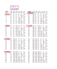
I want to create 5 different delay periods 8;16;24;32 and 40 mins so I propose to remove the 10 way DIL switch and replace it with a 2 pole 6 way rotary switch to allow the options. The DIL switch in the off position allows a +5 signal to the IC and in the on position pulls that signal to Gnd. All but 3 of these connections are either not used at all for the combinations I need or are always used so can be hardwired however there are 3 connections that are used in combinations across the 5 delay periods and I can see there will be a problem with feedback or 'sneak' connections.

My naive electronics 'brain', huh, thinks that a blocking diode in each line would prevent this happening. Anybody got any thoughts ?

Thanks
 
As Geko's website (picprojects.org.uk) has the source code, why not wire up the 5 position switch to 4 or 5 of the input wires that came from the DIP switch, and change the program?

The part that reads the DIP switch is called "readDipSwitch" and it is:-
Code:
unsigned int readDipSwitch (void){

     unsigned char  swdelay = 0;
     unsigned char  swmode = 0;
     unsigned int   delaytime;

     //if (dsw8) { swdelay = 128; }
     //if (dsw7) { swdelay += 64; }
     if (dsw6) { swdelay += 32; }
     if (dsw5) { swdelay += 16; }
     if (dsw4) { swdelay += 8; }
     if (dsw3) { swdelay += 4; }
     if (dsw2) { swdelay += 2; }
     if (dsw1) { swdelay += 1; }

     if (dsw9) { swmode = 4;}
     if (dsw8) { swmode += 2;}
     if (dsw7) { swmode += 1;}
    
    
     switch (swmode) {
    
            case 0: {delaytime = swdelay;} break;          //000  1s-63s,      1 sec int
            case 1: {delaytime = swdelay *  5;}  break;    //001  5s-5m15s,    5 sec int
            case 2: {delaytime = swdelay * 15;}  break;    //010  15s-15m45s, 15 sec int
            case 3: {delaytime = swdelay * 60;}  break;    //011  1m-63m,      1 min int
            case 4: {delaytime = swdelay * 120;} break;    //100  2m-2h6m,     2 min int
            case 5: {delaytime = swdelay * 300;} break;    //101  5m-5h15m,    5 min int
            case 6: {delaytime = swdelay * 600;} break;    //110  10m-10h30m,  10 min int
            case 7: {delaytime = swdelay * 900;} break;    //111  15m-15h45m,  15 min int
           
     }
        return delaytime;
}

If you wire the switch up to dsw1 ... dsw4 corresponding to 16, 24, 32 and 40 minutes, leaving the nothing connected when you want 8 minutes, you could the use:
Code:
unsigned int readDipSwitch (void){

     unsigned int   delaytime = 8;

      if (dsw4 == 0) { swdelay = 40; }
     if (dsw3 == 0) { swdelay = 32; }
     if (dsw2 == 0) { swdelay = 24; }
     if (dsw1== 0) { swdelay = 16; }


        return delaytime;
}

I haven't tested this, but it really is simple enough that it should work. The switches are to ground, so the closed switch reads as 0.
 
Hi guys
Thanks very much for all of this, however, please don't spend too much time on my behalf. The reason I chose this particular project is because of the availability of the IC's already programmed which I've ordered already. I don't yet have a programmer and at the outset I decided that learning to input code to an IC was a learning curve too many in one go !
I'm going to go the signal diode route and complete this project and then try some experimentation with a programmer and firmware to get my head in order. I'd like to copy the software that Diver300 has sent me and play with it later when I've got a programmer and learnt how to do it.

I've got a list of experiments to do like etching PCB's; Drawing Schematics with DesignsparkPCB and I've had some amazing support from a member Eric Gibbs who has suggested using 'Logic Gates', which I thought was an entrance to a field with cows in it ! And they are very confusing !!

Thanks very much
 
hi Stuart,
Looking thru the available Timing Ranges table suggests that the Delay ranges you want: ie: 8, 16, 24, 32 & 40 minutes are not possible with the current PIC program.

It will be necessary to reprogram the 16F628 PIC.
The 3 multiplier Bit switches could be reprogrammed to give combinations for your minutes, keeping the switch Bits 0 thru 6, Set for 1 minute..

Eric
 

Attachments

  • AAesp05.gif
    AAesp05.gif
    11.3 KB · Views: 207
Ah ! In that case I will need toget a programmer and learn how to do that. Is my Word Drawing flawed then ? S
 
hi,
There is an 'add on' option other than reprogramming.

Set the Timer PCB for a 60 sec output, use the output pulse to increment a simple counter IC, select the required minutes delay from the counter outputs.
Would a sketch be more helpful.?

Do you want the driven relay to be ON for the required delay then switch OFF and remain Off.?

E
 
Hi
There's a number of concerns now, not least that based on the conversations in here earlier today and your comments last night, I've now ordered the bits and enclosure etc., including the signal diodes to build the Picproject. I've already ordered, and they have been shipped, 2 PIC16F628A ICs preloaded with the firmware required for this countdown timer. The main reason I chose this particular timer was the availability of the IC with preloaded firmware and I ordered the bits on the basis that having identified the signal diode solution I had everything covered.

I need time to think further, I'll get back to you later
Thanks

S
 
Hi
I've now been back over the process involved and I'm still struggling to understand the problem. The only modification I'm proposing to the original build of the kit is to replace the DIL switch with a Rotary to enable selection of different time periods. If the kit will work with the DIL switch in place it should work exactly the same way with the Rotary in place ie. the common pole wired to Gnd and the settings combination for my time periods wired to each of the Rotary ways in sequence, the only problem being the possibility of feedback of unwanted signals to the IC because of common connections at the Rotary which the inclusion of a signal diode in each line will solve.
I've attached a drawing of this in PDF to explain myself clearly. The signal diodes would be necessary in the lines to and from S4,S5 & S6

What am I missing ?
 

Attachments

  • PIC16F628A to Rotary Switch.pdf
    76.8 KB · Views: 233
hi Stuart,
The table timing periods for SW # 1 thru 6 are for 63 combinations of 1 Seconds to 63 seconds inclusive.

The SW 7 thru 9 are for setting a multiplier of the basic 1 secs thru 63 secs.
So If 9,8,7 are set ON, the Table range is 00 thru 63 secs
If SW ares set to On, On, Off, the 0 to 63 secs are multiplied by 5 , so the timing periods become 5 sec thru 3 min 15secs...

So the possible range delay periods are shown in the upper right side of the Table PDF...

The design of the logic does not allow a 'not used' condition of the SW's, 0 thru 9 will either be read as High or Low and cannot be left disconnected.

Eric
 
Hi Eric

I'm missing this entirely, viz ..

Multiplier - Sw 9 On; Sw 8 Off; Sw 7 Off; would give a multiplier of 1 min ? So Sw 9 needs hard wire to Gnd; In this condition Sw 8 & Sw 7 are Off - not connected to anything ? Therefore not used ?

Timer Period - example - 8 mins - Sw 1 On; Sw 2 On; Sw 3 On; Sw 4 Off; Sw 5 On; Sw 6 On;

24 mins -Sw 1 On; Sw 2 On; Sw 3 On; Sw 4 Off; Sw 5 Off; Sw 6 On;

If you compute this for all 5 time periods Sw 1, Sw 2 & Sw 3 are always On so could be hardwired leaving combinations for Sw 4, Sw 5 & Sw 6

What am I missing ??

S
 
hi,
Look at this marked up 1 minute basic period.
Your rotatory switch combinations must satisfy all the switch positions.

Its possible to have more than one diode per switch contact in order to achieve this timing.

E
If I get a few minutes I will look at creating a diagram

EDIT:
SW 9,7,6 could be hard wired, but SW 1 thru 6 must follow the table
 

Attachments

  • Image1.png
    Image1.png
    22.3 KB · Views: 204
Hi
Yes I understand that, but for all time values S1, S2 & S3 are in identical positions so can also be hardwired ? leaving S4, S5 & S6 to be controlled by the switch ?
S
 
Ah, just spotted on your chart - don't need 1 minute time only 5 options 8,16,24,32 & 40 mins

S
 
hi,
The 1 minute label on my chart was just to highlight that the intervals were for 1 minute, SW 9,7,6 being hardwired to give a 1 min interval.
Do a draft sketch showing your Switched 4 ,5, 6 method, lets see if we can finalise a design today.
You may have to use more than one diode per SW 4,5,6, to rotary switch position in order to get the 'isolated' five timing combinations required.
E
 
Good Morning E

In one of the earlier PM's I sent you a PDF document which shows the layout as a picture and as a chart ?

S
 
Good Morning Ian

That's very kind of you.. ..

However, I have ordered 2 chips from the Picprojects shop and this is as much about me learning my way around the project problems as it is about successfully creating the delay timer. I've recently retired and need something to keep me out of harms way ! I did basic electronics at college 40 odd years ago and I'm enjoying realising how much I don't know !

I appreciate your help
 
hi Stuart,
Look at this simple solution.
Eric
 

Attachments

  • AAesp02.gif
    AAesp02.gif
    9.4 KB · Views: 227
Status
Not open for further replies.

Latest threads

Back
Top