Continue to Site

Welcome to our site!

Electro Tech is an online community (with over 170,000 members) who enjoy talking about and building electronic circuits, projects and gadgets. To participate you need to register. Registration is free. Click here to register now.

  • Welcome to our site! Electro Tech is an online community (with over 170,000 members) who enjoy talking about and building electronic circuits, projects and gadgets. To participate you need to register. Registration is free. Click here to register now.

Powered wheelchair motor. How to make it run?

Status
Not open for further replies.
Oh good. Suggestions worked.

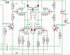
H bridges use 4 transistors, FETS or IGBT's and route a single unipolar power source to a load, typically a motor, that allows up to 4 functions: CW, CCW, brake and coast.
 
Hi,
Here's a 12V HBRIDGE.

Switch 1+4= one direction
2+3 = Reverse
Never switch 1+3 or 2+4 = short circuit
1+2 = Brake
or 2+4 = Brake
Let me know if you intend to make one, you will need more information.
C.
 

Attachments

  • HBRIDGE.jpg
    HBRIDGE.jpg
    167.4 KB · Views: 345
camerart thanks for the info. As I understand this H bridge can be used for changing directions (forward and backward).
Well, I now need to run and control the pair of motors in the wheelchair for commuting around with a joystick. So what do you suggest to use and how?
I want to know if it can be done by Arduino or is there any pre-existing microcontrollers which does the work. Does H bridge help me there?
 
The enable line of an H-bridge effectively can act as a speed control using PWM or Pulse Width Modulation. So FWD/REV are basically easy.

Steering is basically running the motors at different speeds, so that's what your joystick does. You could lock one wheel with the brake when your full left or full right.

When the H-bridge is used for dynamic braking, you can sometimes get away with dissipating the heat in the transistors/FETS alone. Sometimes a resistor is used, What happens is the motor is acting as a generator into a near short circuit, thus it stops quickly.

Regenerative braking is when the motor acts as a generator and instead of dissipating in a resistor or transistor, the energy goes back into the battery.
 
camerart thanks for the info. As I understand this H bridge can be used for changing directions (forward and backward).
Well, I now need to run and control the pair of motors in the wheelchair for commuting around with a joystick. So what do you suggest to use and how?
I want to know if it can be done by Arduino or is there any pre-existing microcontrollers which does the work. Does H bridge help me there?
Hi N,
KSS is correct.
The HBRIDGE is the power section, so you will need as you say a control section. Are you interested in learning about this subject, or just want to get the wheelchair going?

You will need a CONTROL/HBRIDGE circuit for each motor.

I use PICs for control, and don't know much about Arduino apart from many people use them. I can only say, and I may be wrong, that PICs are similar and need a circuit around them, and Arduino have user friendly kits. Maybe Ardiuinos can be used separately like PICs but if they can't then I would learn PICs. Decide carefully!

You will also need to learn a programming language, again choose wisely. C++ seems popular, I used Basic, but it is less popular. (I'm stuck in time!)

The control section sends small usually 5V ON/OFFs to the HBRIDGE (In this case 4 connections) So program it to send 5V to PIN A connected to '1' of the HBRIDGE and it switches 12V to one side of the motor, then switch PIN D connected to '4' and it connect 0V to the other side of the motor= the motor is fully on. If you switch PIN D ON/OFF the motor will stop start, if you switch PIN D quickly (PWM) the motor sees the percentage of 12V the switch is on, so runs slower.

Let me know if this is clear.
C.
 
Thanks KeepItSimpleStupid, camerart
I would definitely would like to learn about the subject. Do you have any website link/source from where I can read about it in detail starting from the basics to the application stage? FYI I am proficient in using C/C++. However I don't know Basic. I am new to electronics and circuit applications. I was learning Arduino nowadays as it is popular. But if something better can be used with my project, please suggest.
 
I dug this out **broken link removed**

Parking, but not brake is probably coast.

TTL logic tends to float high, so in a lot of cases, one uses NOT Enable, so when you disconnect the controller from the motor driver, the motors don;t start running. Processor pins come up in a high Z state and therefore you don't want the motor to move until you have control.

Here's **broken link removed** a much simpler interface, but it won't do for your motor. There's no harm in bringing up the datasheet: https://www.st.com/content/ccc/reso...df/jcr:content/translations/en.CD00000240.pdf

The Canakit has a sense resistor, so you can monitor current. One resistor for both directions. You don't want a roque wheelchair or one that can chop off a limb. Motors draw a big spike of current when they start. Current is proportional to torque. When you use this equation V=Vm-Im*Ra; Vm, you can't measure. Ra is the resistance of the armature. Im is the current through the motor. If you could measure Vm, it would be proportional to speed. That's the basis of a DC tachometer.

An issue with wheelchairs is quiescent power. The Arduino really doesn't have a lot of power management stuff. You may also have to deal with 3.3. and 5V interfacing.

Not really sure what the intention of a wheelchair brake is besides making the turning radius small when you brake one wheel or they use coast and brake to make things cheaper. Brakes can also be controlled with PWM. The brake is probably necessary when using a wheelchair lift.

I'm totally familiar with manual wheelchairs. Me pushing.

So, yea back to your project. With one wheel braked and turning the other, there would seem to be a max speed (PWM percentage) that could be determined. I'd use this as an initial max speed when doing full lefts and rights. You also have ramped starts to deal with. Seat belts? Must you be in the chair? Dead man's switch so to speak.

Then, there is the battery fuel gauge and charging circuits.

I'm throwing out ideas based on what I know without being familiar with an electric wheelchair. The closest thing is a motorized shopping cart.
On/OF with key, FWD/REV, a blinking light when the battery gets low, and a back-up beeper. You also have to be seated properly with no feet on the ground. I'm not sure how they make that happen. With a foot on the floor, it won't go.
 
After all the hard work has been done, here is another suggestion for driving the wheelchair motor:
(1) Use an MC33883 based bridge driver as per figure 14 in the data sheet:
https://cache.freescale.com/files/analog/doc/data_sheet/MC33883.pdf
https://www.digikey.co.uk/product-d...or-nxp/MC33883HEGR2/MC33883HEGR2CT-ND/4780825
(2) Use an Arduino (a Uno clone would be fine) to drive the bridge:
**broken link removed**
(3) The IRF3206PbF NMOSFET would be a good choice:
https://www.infineon.com/dgdl/irfp3206pbf.pdf?fileId=5546d462533600a401535628d64a1ff0


spec
 
Last edited:
Status
Not open for further replies.

Latest threads

New Articles From Microcontroller Tips

Back
Top