Electro Tech is an online community (with over 170,000 members) who enjoy talking about and building electronic circuits, projects and gadgets. To participate you need to register. Registration is free. Click here to register now.
Welcome to our site! Electro Tech is an online community (with over 170,000 members) who enjoy talking about and building electronic circuits, projects and gadgets. To participate you need to register. Registration is free. Click here to register now.
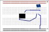
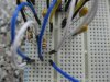
Please disregard the actual resistor shown this is just for illustration. I am trying to understand how it should be connected on a breadboard and I did not realise it was a pot/slider (not too sure of the actual technical meaning).
Please elaborate on what pot/slider mean.
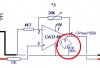
I am also a bit worried about the connection highlight in red in the circuit image.
A breadboard drawing of how they should be connected will be nice.
Thanks a lot
EDIT:
I found this potentiometer on Maplin. So to have this connected will it matter which wire goes where?
hi,
As pointed out by agu,the 10uF are reversed, if you apply 9V to the board they could explode.
Why have you started such a complex project without first getting the basic knowledge regarding components.?
I would suggest if you are interested in building projects you start studying basic electronics.
This is not intended as a 'put down', but doing this project by asking every simple step without understanding each step will not help you to learn.
If you feel you must proceed with this project, forget for the time being the clamp, the AD763 and the PIC and complete the CA3140 amplifier.
You can use a pot as a mVolt dc test source.
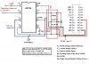
Once you have got that working, program the PIC to read the voltage coming from the CA3140.
It was not my intention to go as far as I did. I thought it would be a simple easy job. Obviously I was wrong and it got complicated gradually.
I also assumed this is a problem that has already been solved and the solution should be readily available, so I did not give too much attention to the transducer-AD736-PIC part and implemented the software client/server simulating the input signal to the PIC, which works fine.
I now decided to tackle the final part. This is becoming a project on its own
At this point it will be a total waste to stop.
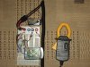
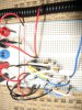
With regards to the capacitors the ones I have, do not have any + or - signs so I initially assumed it will be ok to plug them.
The ones in the diagram obviously show a +++ sign but not the ones I am actually using.
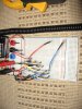
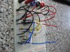
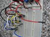
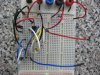
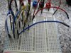
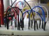
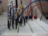
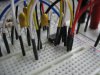
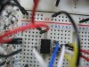
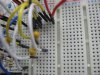
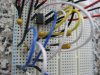
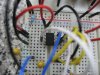
I will try this evening to post pictures of my capacitors, the spot and the board I am using.
I ordered the CA3140 and a new larger breadboard, with new correct size capacitors. should be arriving in the next couple of days.
I am looking at this pot for pin 2 to 6 any recommendations? Also what happens to the 3rd pin in this case? one end is connected to 2 the other to 6 and the 3rd to..?
Thank you for your patience in helping me to solve my electronics component problems and I must say without your support I would not have gone this far.
hi,
As pointed out by agu,the 10uF are reversed, if you apply 9V to the board they could explode.
Why have you started such a complex project without first getting the basic knowledge regarding components.?
I would suggest if you are interested in building projects you start studying basic electronics.
This is not intended as a 'put down', but doing this project by asking every simple step without understanding each step will not help you to learn.
If you feel you must proceed with this project, forget for the time being the clamp, the AD763 and the PIC and complete the CA3140 amplifier.
You can use a pot as a mVolt dc test source.
Once you have got that working, program the PIC to read the voltage coming from the CA3140.
Remember you are working with millivolt level ac signals.
You must keep the interconnecting wires as short as 'reasonable' else you will pick up mains em radiation which will give reading errors.
I would recommend that you build the CA3140 amplifier, this will increase the voltage that is output from the AD736.
You can use your dc meter to check the output.
Use a pot about 10k or 20K as a test input source for the amplifier.
This site uses cookies to help personalise content, tailor your experience and to keep you logged in if you register.
By continuing to use this site, you are consenting to our use of cookies.

![bblinks[1].GIF](/data/attachments/20/20271-b14bd7c4cb813f75b1f41eaaa422bb7f.jpg)
![bblinks[1].GIF](/data/attachments/20/20272-2325a969df9f6b50d378c89dc1d4b8b5.jpg)

") .
.