Continue to Site

Welcome to our site!

Electro Tech is an online community (with over 170,000 members) who enjoy talking about and building electronic circuits, projects and gadgets. To participate you need to register. Registration is free. Click here to register now.

  • Welcome to our site! Electro Tech is an online community (with over 170,000 members) who enjoy talking about and building electronic circuits, projects and gadgets. To participate you need to register. Registration is free. Click here to register now.

Power sensor signal conditioing

Status
Not open for further replies.
Thanks Eric,

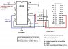
My multimeter show 200, 600 for AC and 200m, 2000m, 20,200,600 for DC.

Find attached a picture my multimeter.

The Clamp meter is supposed to be plugged into a multimeter so it has the same socket leads as my multimeter, so I can remove my test leads and place the clamp leads instead.

I will try putting the clamp on the mains live power supply this should be well over 2KW.

I will let you know how it goes with that, however I am still a bit doubtful, I think I need a wider range multimeter.


Thanks again.

Edit:

Just tested it and put the dial on 200m, the reading was fluctuating between 0 and 00.1 which increased when I touched the clamp cables :)
I had my washing machine on the kettle most of the light, 2 TV's a 2 computers on I would this is well over 2 KWH.


Whats the lowest range on your ac DMM.?

EDIT: the most sensitive range is the 1mV/0.1Aac.

Does your clamp require that you clamp only one of the conductor pair.?

A 2KW electric fire or electric kettle would be a good load test.
The 2KW fire should give about 80mVac output.
 

Attachments

  • a987_1[1].jpg
    a987_1[1].jpg
    22.2 KB · Views: 158
Last edited:
Your "el-cheapo" multimeter cannot measure AC-millivolts. Its AC-volts ranges are only 200V and 600V. If it is set to 200V then the lowest it measures is 0.1V which is 100mV.

The clamp is supposed to circle only one wire of a two-wires appliance.

My Fluke multimeter has 400.0mV as its most sensitive AC-volts range so I can see 0.1mVAC.
 
I suspected that. Just checked the manual and it says resolution is 100mv.


The clamp circles the live wire that is correct.

How can I test if my capacitor is giving me problems with this multimeter?


Thanks.


Your "el-cheapo" multimeter cannot measure AC-millivolts. Its AC-volts ranges are only 200V and 600V. If it is set to 200V then the lowest it measures is 0.1V which is 100mV.

The clamp is supposed to circle only one wire of a two-wires appliance.

My Fluke multimeter has 400.0mV as its most sensitive AC-volts range so I can see 0.1mVAC.
 
I suspected that. Just checked the manual and it says resolution is 100mv.

How can I test if my capacitor is giving me problems with this multimeter?
Thanks.

hi,
The 16uF should not give a problem, look at this image.

Post the full circuit showing the component values etc.
 

Attachments

  • CAvg1.gif
    CAvg1.gif
    51.2 KB · Views: 170
Last edited:
Hi Eric,

I replaced my capacitor with a code 104 Mylar.

my current circuit looks like the attached image. On pin 1 & 2 the clamp red and blakc leads with the mylar capacitor on pin 1.

Pin 4 & 7 connected to battery.

Ouput and 4 connected to my multimeter.

When I remove the batteries and I set my multimeter to 0.2vdc I can see a small change (I suspect noise), but it does not reflect the actual load I have on the clamp meter.

I have ordered a better multimeter little bit more expensive than the one I have :) .

Thanks


hi,
The 16uF should not give a problem, look at this image.

Post the full circuit showing the component values etc.
 

Attachments

  • connection.JPG
    connection.JPG
    31.7 KB · Views: 213
hi,
As I read the datasheet 2 * 1.5V batteries will not be acceptable as a power supply.
Look at the datasheet for the Vref conditions when using low voltage supplies.

I did point this out in an earlier post.:)
 

Attachments

  • esp11 Nov. 10.gif
    esp11 Nov. 10.gif
    10.1 KB · Views: 132
  • esp10 Nov. 10.gif
    esp10 Nov. 10.gif
    6.7 KB · Views: 126
Last edited:
the table shows that for:
200mv rms sine wave input: ± 5
Zero signal it should be ±16.5

Where does my transducer input supply fall? i do not think it will exceed 200mv.

Please bare with me I am in an uncharted territory here. :confused:

And to supply 16 volts I can just a use a standar variable adaptor which I think you mentioned in an earlier thread.

One more thing how do I get 0 volts? there seem to be references to negative and zero.

Thanks

hi,
As I read the datasheet 2 * 1.5V batteries will not be acceptable as a power supply.
Look at the datasheet for the Vref conditions when using low voltage supplies.

I did point this out in an earlier post.:)
 
the table shows that for:
200mv rms sine wave input: ± 5
Zero signal it should be ±16.5

Where does my transducer input supply fall? i do not think it will exceed 200mv.

Please bare with me I am in an uncharted territory here. :confused:

And to supply 16 volts I can just a use a standar variable adaptor which I think you mentioned in an earlier thread.

One more thing how do I get 0 volts? there seem to be references to negative and zero.

Thanks
hi,
Look at fig28 of the datasheet, this shows operation from a single 9V battery
[ or single power adaptor rated at 9Vdc or 12Vdc REGULATED, at say 100mA.

The ref to negative and zero is when a single or dual power supply is being used.
Zero is often referred to as common/gnd.

Whats the maximum current you are planning to measure, this will give you a guide to the output of the current clamp.
Let me know.:)

Realise that the AD736 ic is a true absolute rms/average convertor, this means if you have a ac signal from the clamp of say 140mVac peak the convertor will output 100mVdc [rms value]
 
Last edited:
Thanks.

the clamp will give me 1mv per 0.1 Amp of load
or 1mv per 1 Amp of load, depending on the switch settings on the clamp itself.

So a 5Amp load will give me 50mv on one settgins and 5mv on the other.

so for an averrage housgol I would say about 10-20Amps which is about 200mv on setting one and 20mv on setting 2.

If I can be felixible with the maximum being whatever the clamp can read that will be good otherwise I do not mind a compromise which is why I opted for the 200mv as being a sensible figure.

With regards to the ground or zero I will then need to connect a ground line to the bread board?


Regarding the power : do you think 9V will be enough?

and in relation to figure 28 they connected pin 3 to 6 through an optional 10µf (so to my multimeter I need to connect 6 (to red lead ) and 3 (to black lead) in order to get readings?)

pin 4 to 5 and to 7 through a couple of resistors 100κΩ each. so do I need any of this?

Or have missed the plot here? :D

hi,
Look at fig28 of the datasheet, this shows operation from a single 9V battery
[ or single power adaptor rated at 9Vdc or 12Vdc REGULATED, at say 100mA.

The ref to negative and zero is when a single or dual power supply is being used.
Zero is often referred to as common/gnd.

Whats the maximum current you are planning to measure, this will give you a guide to the output of the current clamp.
Let me know.:)

Realise that the AD736 ic is a true absolute rms/average convertor, this means if you have a ac signal from the clamp of say 140mVac peak the convertor will output 100mVdc [rms value]
 
Thanks.

If I can be felixible with the maximum being whatever the clamp can read that will be good otherwise I do not mind a compromise which is why I opted for the 200mv as being a sensible figure.
I would choose the 200mV for the best resolution.

With regards to the ground or zero I will then need to connect a ground line to the bread board?
No, dont connect an Earth wire, if thats what you mean by ground.

Regarding the power : do you think 9V will be enough?
I would chose about 9V

and in relation to figure 28 they connected pin 3 to 6 through an optional 10µf
The 10uF is for extra filtering, I would only fit that if required after testing the AD763 in order to see what results you get.

(so to my multimeter I need to connect 6 (to red lead ) and 3 (to black lead) in order to get readings?)
The two 100K's divide/split the 9V supply into +/- 4.5V, the centre junction of the two 100K's a virtual ground

pin 4 to 5 and to 7 through a couple of resistors 100κΩ each. so do I need any of this?
Use you DMM connected to the junction of the 100K's [black wire] and pin 6 [red wire]

Or have missed the plot here? :D

Hi,
Your problem with using a single supply split in this way is that the Output pin3 will always have +4.5Vdc with rectified signal added to it with respect to COM pin 8.
This is because the negative end of the 9V battery will be common connection to the PIC's 0V.!

To avoid this problem you will have to use an isolated 9Vdc supply for the AD736 and a separate +5Vdc for the PIC. [ a 9V battery would be the simple way to power the AD736]

The PIC 0v would then be connected to the junction of the 100K's and the PIC adc input to pin 6 of the AD736.
All the pIC will see is the rectified signal , no standing +4.5V.

I hope you follow that, if not please :)ask.
 
Last edited:
Right,

I think I follow most of your explanations.

But I need to clear few things:

The negative end of the battery is connected to pin4, and also this should be connected to pin 5 through a 33µf, and to 7 through a couple of 100κΩ resistors, and from between the two resistors to pin 8.

I also need to connect negative to pin 7 through two 4.7µf capacitors and link to pin 8.

basically what is in figure 28 with exception of:
pin 3 to 6
pin 8 to 1
and the way pin 2 is connected.

The PIC does not require any power and it has its own battery and can provide +5v if need be. So how should the isloation of the battery be done?


From the provided image the blue is what I do not have connected at the moment and the red are the queries.

Do I need to connect all what is in blue as is.

Thanks a lot.

Hi,
Your problem with using a single supply split in this way is that the Output pin3 will always have +4.5Vdc with rectified signal added to it with respect to COM pin 8.
This is because the negative end of the 9V battery will be common connection to the PIC's 0V.!

To avoid this problem you will have to use an isolated 9Vdc supply for the AD736 and a separate +5Vdc for the PIC. [ a 9V battery would be the simple way to power the AD736]

The PIC 0v would then be connected to the junction of the 100K's and the PIC adc input to pin 6 of the AD736.
All the pIC will see is the rectified signal , no standing +4.5V.

I hope you follow that, if not please :)ask.
 
Right,

I think I follow most of your explanations.

But I need to clear few things:

The negative end of the battery is connected to pin4
Yes
, and also this should be connected to pin 5 through a 33µf,
Yes
and to 7 through a couple of 100κΩ resistors,
Yes
and from between the two resistors to pin 8.
Yes

I also need to connect negative to pin 7 through two 4.7µf capacitors and link to pin 8.
Yes
basically what is in figure 28 with exception of:
pin 3 to 6
pin 8 to 1
and the way pin 2 is connected.

The PIC does not require any power and it has its own battery and can provide +5v if need be.

So how should the isloation of the battery be done?
Use a 9V battery for the AD736 and separate battery for the PIC.

Connect the negative end of the PIC battery to the junction of the two 100K's and pin6 [output] to the PIC adc input,

From the provided image the blue is what I do not have connected at the moment and the red are the queries.

Do I need to connect all what is in blue as is.

Thanks a lot.

hi,
You most likely will need an amplifier between pin 6 and the PIC's adc input.

Please draw out the complete circuit for the AD736 , showing also the PIC adc connection and the batteries then post it.
 
hi,
You most likely will need an amplifier between pin 6 and the PIC's adc input.

Please draw out the complete circuit for the AD736 , showing also the PIC adc connection and the batteries then post it.


Here is what I think I might need to do.

Comments are on the diagram.

One more thing: with regards to the 2 X 4.7µf capacitors: I can not find an exact 4.7 or is this supposed to be 4n7 or 0.047µf?? I have a bag of over 100 capacitors of all sizes so I am too sure of the nearest appropriate size.

Note:

See edemoboard:

https://www.electro-tech-online.com/custompdfs/2008/11/SunSPOT-TheoryOfOperation.pdf

Thanks.
 

Attachments

  • chip circuit.JPG
    chip circuit.JPG
    60.6 KB · Views: 191
Last edited:
update:

I connected as in the diagram.

The 33µf capacitor was replaced with a 33n one.
The two 4.7µf capacitors were replaced with 4n7 ones.

Connected 9VDC Adaptor.

Connected my clamp.

plugged my multimeter with the dial on 200m :

It shows 00.5 when nothing is connected.
I connect the clamp with almost 40 watts of load, nothing much changes probably 00.6.
I plug a hair dryer 2000w on hot and it jumps to 01.3

And it is pretty much consistent.
 
update:

I connected as in the diagram.

The 33µf capacitor was replaced with a 33n one.
The two 4.7µf capacitors were replaced with 4n7 ones.
Recheck these two caps values you have chosen as equivalents.
µ, means microfarad [ 10^-6]. n, means nanofarad. [10^-9] !


Connected 9VDC Adaptor.

Connected my clamp.

plugged my multimeter with the dial on 200m :
I assume this is the 200mV dc range

It shows 00.5 when nothing is connected.
I connect the clamp with almost 40 watts of load, nothing much changes probably 00.6.
40W at 240Vac is 0.17A, thats approx 1.7mV.
I plug a hair dryer 2000w on hot and it jumps to 01.3
Thats 2000W/240 =app 8A, should read about 80mV

And it is pretty much consistent.

I'll look thru your drawing.

EDIT: You can see from the low mVdc levels on the output of the AD736 that you will require a amplifier between the AD763 output and the PIC adc input.
 

Attachments

  • AD763opa1.gif
    AD763opa1.gif
    88.4 KB · Views: 168
Last edited:
Ok Thanks for the response.

I will need to buy a CA3140 Chip.

EDIT: I found the CA3140EZ in Maplin : is it the same?

I also need a list of the capacitors/resistors that I need to get it connected.
- to pin 2 I need a 4k7 resistor??
- to pin 3 I need 10k resistor
- to pin 1 & 5 I need 10k resistor.
- between 2 and 6 I need 20k something multiplied by 3? :confused:

I will also need to buy the correct size capacitors.

1 x 10µf
2 x 4.7µf
1 x 33µf

Thanks a lot.


I'll look thru your drawing.

EDIT: You can see from the low mVdc levels on the output of the AD736 that you will require a amplifier between the AD763 output and the PIC adc input.
 

Attachments

  • CA3140.JPG
    CA3140.JPG
    21.8 KB · Views: 201
Last edited:
On the diagram provided there is a variable resistors is that correct?

A 20K one and the 3 means set to 3 volts?

Is that correct?

Ok Thanks for the response.

I will need to buy a CA3140 Chip.

EDIT: I found the CA3140EZ in Maplin : is it the same?

I also need a list of the capacitors/resistors that I need to get it connected.
- to pin 2 I need a 4k7 resistor??
- to pin 3 I need 10k resistor
- to pin 1 & 5 I need 10k resistor.
- between 2 and 6 I need 20k something multiplied by 3? :confused:

I will also need to buy the correct size capacitors.

1 x 10µf
2 x 4.7µf
1 x 33µf

Thanks a lot.
 
On the diagram provided there is a variable resistors is that correct?

A 20K one and the 3 means set to 3 volts?

Is that correct?

hi,
The *3 indicates the 20K pot is set to give a Gain of 3 from the CA3140.

The 10K [pin 1and 5] pot is to trim the CA3140 zero when there is no input.

EDIT:
the gain of *3 is assuming that 1Vdc output from the AD736 when measuring 100Amps.

You could adjust the gain to suit your requirement.
 
Last edited:
right,

So only one variable resistor of 20k set to * 3 gain? (can you give me a link to one?)

And what about the 4k7 resistor what will the actual resistor size be here?

Something else:

pin 1 & 5 are connected to negative and to each other as in the image provided?

Thanks


hi,
The *3 indicates the 20K pot is set to give a Gain of 3 from the CA3140.

The 10K [pin 1and 5] pot is to trim the CA3140 zero when there is no input.

EDIT:
the gain of *3 is assuming that 1Vdc output from the AD736 when measuring 100Amps.

You could adjust the gain to suit your requirement.
 

Attachments

  • bblinks[1].GIF
    bblinks[1].GIF
    8.6 KB · Views: 134
Status
Not open for further replies.

Latest threads

New Articles From Microcontroller Tips

Back
Top