Continue to Site

Welcome to our site!

Electro Tech is an online community (with over 170,000 members) who enjoy talking about and building electronic circuits, projects and gadgets. To participate you need to register. Registration is free. Click here to register now.

  • Welcome to our site! Electro Tech is an online community (with over 170,000 members) who enjoy talking about and building electronic circuits, projects and gadgets. To participate you need to register. Registration is free. Click here to register now.

Power sensor signal conditioing

Status
Not open for further replies.

charbel89

New Member
Hi,

I am not sure if this is the right forum for my question, please let me know if it is not.


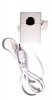
I have sensor that is supposed to be clamped around a live wire and this will produce some form of signal. The sensor has no power supply and it is rather a cicular magent with a copper coil wrapped around. It also has two wires.

Checking the sensor with my multimeter it shows 49.2 ohms when my digital multimeter ohm is set to 200.

The voltage when set at 200k fluctuates (clamped around a live cable) between -1.5 and 1.5. The fluctuation changes to between -1.8 to 1.8 or -1 to 1 or -0.5 to 0.5 depending on live cable load.

The maximum amps this sensor supports is 70AMPS and minimum that can be detected is 15 watts / 0.065 AMPS.

I need to convert this signal into a voltage between 0 and 3 volts to allow me to make accurate readings of the actual power load on the live cable. So somehow the minimum and maximum of the sensor should map to the 0 to 3 volts range.

I need to interface this sensor with an ADC that only accepts up to 3 volts and is 10 bits i.e. the maximum is 1023 digital input.

I have worked out the table below:
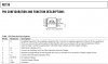
9 8 7 6 5 4 3 2 1 0
Watts 15400 7700 3850 1925 962.50 481.25 240.63 120.31 60.16 30.08
Mv 3000 1500 750 375 187.50 93.75 46.88 23.44 11.72 5.86
Digital 512 256 128 64 32 16 8 4 2 1


Can anyone advice on what I need to do in order to make some sense of the readings. Currently when I read my ADC which is pointing to raw data from sensor I get values fluctuating between 0 and 1023. What I really need is to filter or condition the signal such that it is a true representative of the live cable load.


Many thanks in advance


Regards

Charbel
 
hi,:)
The current transformer will output 'ac', you need to use a precision rectifier to convert the 'ac' signal to 'dc', then smooth this dc before its sampled by the adc.

Do you follow OK.?

EDIT: like this.
 

Attachments

  • esp01 Oct. 05.gif
    esp01 Oct. 05.gif
    10.4 KB · Views: 238
Last edited:
Thanks for the quick response Eric.

From the readings I did notice it was fluctuating which meant it was AC.

So will need to convert to DC and then condition the signal.

In this case i will need to devices connected right?

In simple english :) what are they called and where can I buy them from and are there different models/capabilites etc...

Many thanks again


Regards

hi,:)
The current transformer will output 'ac', you need to use a precision rectifier to convert the 'ac' signal to 'dc', then smooth this dc before its sampled by the adc.

Do you follow OK.?

EDIT: like this.
 
hi,

Here is one link, it has values and notes

**broken link removed**

also these 2 pdf's should help.
 

Attachments

  • fullrect.pdf
    10.6 KB · Views: 229
  • precrect1.pdf
    248.2 KB · Views: 1,095
Can I buy a ready assembled one that meets the requirements off the shelf?

:eek: it is going to take me months to assemble one of those.

The sensor has two wires so this means that I have to plug two wires in and get one out :confused:.

The out signal will then be connected to my ADC.

Please excuse my lack of understanding I am new to all this and I am trying to make some sense of what I need to do to interface the two devices. I can do the coding part but not the hardware side of it.

Many thanks for your time and efforts
 
Can I buy a ready assembled one that meets the requirements off the shelf?

:eek: it is going to take me months to assemble one of those.

The sensor has two wires so this means that I have to plug two wires in and get one out :confused:.
One wire is connected to 0V

The out signal will then be connected to my ADC.

Please excuse my lack of understanding I am new to all this and I am trying to make some sense of what I need to do to interface the two devices. I can do the coding part but not the hardware side of it.

Many thanks for your time and efforts

hi,
Look at these, AD736 links.

http://uk.farnell.com/jsp/search/browse.jsp?N=500005+1002466&Ntk=gensearch_001&Ntt=AD736&Ntx=

http://search.analog.com/search/def...y=precision+rectifier&contentType=Data_Sheets
 

Attachments

  • AD736.pdf
    572.1 KB · Views: 344
Thanks again.

That looks like exactly what I need.

Which one is recommended out those two? the AD736JNZ and AD736JRZ , the difference seems to be in bandwidth and accuracy precentage.


So looking at the provided diagram I will need to identify what to connect where.

My two pin outputs of the sensor: does it matter how they are soldered in and which pins should they be soldered into.

My power supply: do I need to plug only the positive +3 volts? or do i need negative as well or ground, diagram seems to indicate yes we i need ground (pin 4 and 7).

My output will be the only result (pin 6) that I can connect to my ADc or do i need to still condition the signal (smoothen) further prior to connecting it?

Thanks.
 

Attachments

  • AD736 connections.JPG
    AD736 connections.JPG
    154.2 KB · Views: 202
I think the clamp-on sensor must be clamped around only a single wire in a power cable because if clamped around both wires then the signal is cancelled.
 
That is correct. this version only works on a single live wire.

I have seen other clamp ons that work on both and up to 3 wires bundled in a cable.

mine is a pretty simple version.

I think the clamp-on sensor must be clamped around only a single wire in a power cable because if clamped around both wires then the signal is cancelled.
 

Attachments

  • 53111.jpg
    53111.jpg
    19 KB · Views: 200
Here is the one that can deal with 3 cores:

https://www.tequipment.net/MeggerMMC850.html

In my case I am not too bothered really, I just need to be able to read the sensor by interfacing it with an ADC device that supports 10 bits i.e. 1023 integers (Up to 3 volts max).

As Eric pointed out to me I need a rectifier and then to smooth the signal, and he pointed me to the AD736 IC which seems to be the one I need, however I am just a bit confused as to which version shall I buy, exact connection details and whether I still need to condition my signal any further before interfacing with the ADC.

Many thanks.
 
Last edited:
Here is the one that can deal with 3 cores:

https://www.tequipment.net/MeggerMMC850.html

In my case I am not too bothered really, I just need to be able to read the sensor by interfacing it with an ADC device that supports 10 bits i.e. 1023 integers (Up to 3 volts max).

As Eric pointed out to me I need a rectifier and then to smooth the signal, and he pointed me to the AD736 IC which seems to be the one I need, however I am just a bit confused as to which version shall I buy, exact connection details and whether I still need to condition my signal any further before interfacing with the ADC.

Many thanks.

hi,
The only difference between the two versions is one is surface mount and the other is DIP.
I would suggest a DIP version as you are experimenting, it will plug into your project board.

Read and understand the AD736 datasheet.:)

Get the ic working in the project board, examine the output from the AD736 then decide if extra conditioning is required.

What exactly are you doing with this project.? I know it measures 'ac' current in a mains line.!
But, why and how are you going to display the current.?
 
Eric,

Many thanks for your assistance.

I was wondering when were you going to pop the question :) .

I am actually attempting to interface it with a Java Sunspot.

The eDemoBoard that comes with the spot has ADC connectors. As it stands the readings I was getting from the sensor were all over the place random numbers between 0 and 1023 (10 bit ADC). The spot uses ADT711 IC.

I really know nothing about electronics and I was lucky I didn’t damage my spot because had the current been above 3 volts it would have damaged some IC's inside.

I get confused with all this electronics jargon and every time I come across a technical term I have to go back and work out what it actually is.

I am also looking for the bits that simplify the connectivity with the sunspot. I am not sure if there any better place than Maplin or Farnell.

I am looking for the pcb socket one which should give me 0.025" pins to plug the female wires into. (do not know where I can find them in the UK.)

My soldering skills suck :eek: .

Thanks a lot.


Regards


Charbel

hi,
The only difference between the two versions is one is surface mount and the other is DIP.
I would suggest a DIP version as you are experimenting, it will plug into your project board.

Read and understand the AD736 datasheet.:)

Get the ic working in the project board, examine the output from the AD736 then decide if extra conditioning is required.

What exactly are you doing with this project.? I know it measures 'ac' current in a mains line.!
But, why and how are you going to display the current.?
 

Attachments

  • TD.GIF
    TD.GIF
    4.6 KB · Views: 163
  • JumperWire-Female-01-L.jpg
    JumperWire-Female-01-L.jpg
    185.9 KB · Views: 168
Eric,
The spot uses ADT711 IC.

I am also looking for the bits that simplify the connectivity with the sunspot. I am not sure if there any better place than Maplin or Farnell.

I am looking for the pcb socket one which should give me 0.025" pins to plug the female wires into. (do not know where I can find them in the UK.)
Regards
Charbel

hi,
One of the standard pitches is 0.1inch.
The leads you have posted have sockets, you say you want sockets for the pcb.???

I'll look at the ADT711.

Why have you chosen to go the SPOT route.?

EDIT:
Having trouble getting the ADT711 datasheet, can you post it.?
 
Last edited:
Actually I do not have the sockets nor the jumper wires leads. The spot has 10 pins in two rows and comes with a female connector that need to be sodlered in, I however was looking for a male one where I can solder it in (Like the on ein above pic) and then the female jumper wires can be easily plugged and unplugged at will.

As for the reasoning behind the spot choice, was that I am a java programmer and the spot makes life easy for me I can write the code to do all I wanted to do myself.

Also this project is just one I may have other projects, so it is easy to almost interface it with anything.

The IC is actuall ADT7411 sorry.

Regards


hi,
One of the standard pitches is 0.1inch.
The leads you have posted have sockets, you say you want sockets for the pcb.???

I'll look at the ADT711.

Why have you chosen to go the SPOT route.?
 

Attachments

  • 278713242ADT7411_prg.pdf
    291 KB · Views: 201
Last edited:
Last edited:
Thanks I will look into these.

I not so sure if I need all the channels really. The sensor I have has two wires so this means those will need to go somewhere on the AD736, Presumbaly it will need some form of power so the spot can provide 3 or 5 volts and GND as well and I guess the end result will be on the output channel.

However I am not so sure where I should connect my sensor and wires to exactly. I have a vague idea, but I do not want to damage the IC :) .

I am assuming I will then take the output and plug it into one of the ADC slots on the spot edemoboard.

Any other tips will be very much appreciated.


hi,

Look at these pcb pin connectors, you can also buy the mating socket inserts.

https://uk.farnell.com/1554030/connectors/product.us0?sku=tyco-electronics-amp-5103308-7

https://uk.farnell.com/9730990/connectors/product.us0?sku=molex-22-04-1101

EDIT:
Do you plan to use all 8 adc channels and the tempr channel.?
 
Thanks I will look into these.

However I am not so sure where I should connect my sensor and wires to exactly. I have a vague idea, but I do not want to damage the IC :) .

I am assuming I will then take the output and plug it into one of the ADC slots on the spot edemoboard.

Any other tips will be very much appreciated.

Look at page 13 of 20 of the AD736 datasheet for the 'ac' coupled application examples.

Have you already bought the ADT7411, if not, look at the MCP3202 adc [spi/i2c] Farnell.
 
Last edited:
Look at page 13 of 20 of the AD736 datasheet for the 'ac' coupled application examples.

Have you already bought the ADT7411, if not, look at the MCP3202 adc [spi/i2c] Farnell.

The spot comes with eDemoBoard that is already using the ADT7411 and provides for the ADC input to the spot, it has 6 input A0-A3 and A4 & A5 I think.

Checking page 13 out confuses the hell out of me :eek: .

Since my sensor is producing AC I presume it will have to be either Figure 21 or 23.

I will put my money on Figure 23. :D

I will assume that my sensor will be connected to pin 1 & 2.
+3V to pin 7.
GND to 4
6 is my output.

Just to confirm the DC output will range from 0 to 1.7 based on 2.8 V input right as per the diagram shown?
 

Attachments

  • AD736 connections-2.JPG
    AD736 connections-2.JPG
    17.8 KB · Views: 181
  • AD736 output.JPG
    AD736 output.JPG
    20 KB · Views: 159
The spot comes with eDemoBoard that is already using the ADT7411 and provides for the ADC input to the spot, it has 6 input A0-A3 and A4 & A5 I think.

Checking page 13 out confuses the hell out of me :eek: .

Since my sensor is producing AC I presume it will have to be either Figure 21 or 23.

I will put my money on Figure 23. :D

I will assume that my sensor will be connected to pin 1 & 2.
+3V to pin 7.
GND to 4
6 is my output.

Just to confirm the DC output will range from 0 to 1.7 based on 2.8 V input right as per the diagram shown?

hi,
As I read it, pin 1, using a series capacitor for one sensor wire and
pin2 for the other.[0V]

Pin7 +3V
Pin4 -3.4V
Pin 6 output.

What type is your current transformer.?
 
Last edited:
Oh I missed the capacitor part :confused: .

This means that I need to have a capacitor between the sensor and my pin 1?.

The transformer is just wrapped around one side of the magent, I do not have any specs for it but as in my first post i was able to get some readings regarding the ohms, I do not know if this helps.


hi,
As I read it, pin 1, using a series capacitor for one sensor wire and
pin2 for the other.[0V]

Pin7 +3V
Pin4 -3.4V
Pin 6 output.

What type is your current transformer.?
 
Status
Not open for further replies.

Latest threads

New Articles From Microcontroller Tips

Back
Top