Electro Tech is an online community (with over 170,000 members) who enjoy talking about and building electronic circuits, projects and gadgets. To participate you need to register. Registration is free. Click here to register now.
Welcome to our site! Electro Tech is an online community (with over 170,000 members) who enjoy talking about and building electronic circuits, projects and gadgets. To participate you need to register. Registration is free. Click here to register now.
Why the 15 ohm resistor to the gate??? as you can not switch a thyristor off by the gate, this was said right back in the early posts.
The data sheet said logic level gate and by memory it should switch on with around 20 mA source and with the 15 ohm resistor in there the opto coupler needs to handle 333mA or 1/3 of a amp at 5 volts, and i dont think it is rated that high.
Your link is broken and dont work so i cannot see the setup.
Is it firing when you are connecting the input cable to the computer?
If so this is because the inputs to the driver chips are floating prior to the computer being connected and is why the outputs are firing, it would make more sense to add a pullup or pulldown resistors (depending on the logic from the pc) to the inputs on the drivers so they are not floating prior to cable connection.
Something like a 4K7 or 10K should be enough to hold the inputs to a logic level and prevent them from floating.
Again a simple schematic would answer many questions.
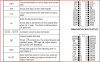
Here is a snipit from the driver data sheet and if you read the data sheet it says........If OE is held active high ALL outputs are switched off, so by placing a pullup resistor on the OE input it should switch off all the outputs untill the PC takes the OE input low enabling the outputs.
Even though the driver has a pullup internal on the OE input it might not be enough for the setup you have and also require the external pullup as well.
The LE input has a internal pulldown resistor and this might also require a external pulldown as well, as there is now values given for the internal resistors.
The Thyristor is SUPER sensitive. That's why the 15ohm resistor is there, it also pulls the gate low again causing the gate to close. When ever I would hook my VGA cable up to the gates it would open the gate, or when i would any pin power, all 15 thyristors would fire. But would a diode work? So that it had to reach a certain voltage? Or is it the leds causing the sensitive gate? If so I can remove them, I like to keep them, one is to tell me when I have a live firework, the other is a test led for Grinch, and they both barely turn on to tell me that the board has power. I think thats why its sensitive.
Or hey, why don't I just buy a OPTO that can handle like 1A or at least 500mA? That way I dont have to change anything?
UPDATE, Did some looking, they are hard to find and im headed to work. Forget price, I NEED these things soon, or i'm gonna be to late.
I check in as soon as i get home.
But also what voltage would I need to reach in order to drop the mA low enough for the OPTO to handle it? It said it can handle 70V, but would the Thyristor handle that?
Back up a little, you are missing the point here!!!!!
You need to ask why the scr's are firing when they should not be.
The scr's can only fire when they are receiving a signal to fire them, and "where is that coming from" is the question you need to ask yourself.
You have a aproach of adding bandaids to fix the problem and not finding the problem.
We need to fix the source of the problem and not add bandaids to the problem.
As i stated i think the problem is with the driver inputs floating and this will cause the drivers to fire the outputs (scr's) a few hundred times a second hence all SCR's on.
There is no reason the circuit wont work when configured correctly.
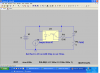
For my sanity draw me a circuit diagram and if you want or need then send me a PM and i will give an email address you can send it to, as you have trouble posting it to the forum.
Why the scrs are firing is because of the leds in the circuit. That I have to have. The driver wasn't even hooked up when the scrs are so sensitive, therefore I know that isn't it. I drew a very rough diagram of it. Did it not work again? If not it is in my album called "Ideas".
I know that in order to have the Hot and Test LEDS, that I have to have a 15ohm resistor on the gate. I have tested and tested and tested this. I know for sure now that's what it is. So it isn't a band-aid, its a unexpected problem, due to lack of knowledge on my part.
So either I need to find a voltage high enough to lower the amps down so the OPTO can handle it at 50-60mA. Or i need a OPTO that can handle 330-500mA.
Cause I need everything in the circuit....... Sadly....
It should work, but i think you have a dogs breakfast of a circuit and its hard to know what will or wont work with a mismatch of components.
If cost is not an issue than the simplest way would be to scrap the SCR's and optos etc, and just use a solid state relay directly off the driver, as a solid state relay is what you are trying to create with the opto and scr anyway.
That way you would have it all in a single package that is designed correctly to work and it will switch ON and OFF.
You should be using 24 volts to over come the interconnect wire resistances. The E-Matchs are about 1 to 2 ohm load with an all fire current of over 1 amp.
Sometimes thay will short after firing!
Test current should be less than 5ma.
Thare are many better ways to fire E-Matchs than with lighting controls!
I have done both and would never use lighting controls for pyro.
Thanks again 4pyros, but this system is way cheap and better, because my E-matches CANT short out..... hmmmm sounds like a new better invention. That can only be made when people get out of the box and invent. 24V is a pain. I like simple yet effective.
This site uses cookies to help personalise content, tailor your experience and to keep you logged in if you register.
By continuing to use this site, you are consenting to our use of cookies.