thekyguy11
New Member
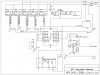
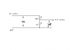
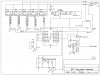
I am building a device to replace the ignition switch on my car. I have already written the code for the PIC18f1320 (thanks to everyone who has helped me so far), and I have attached my schematic that I drew up on Express Schematic software. I'm kind of learning as I go, so I figure there has to be at least a few "Rules of thumb" that I am violating with this. Plus, there are a few values that I am not sure of. I also attached the LM2917 data sheet and the diagram I got the LM7805 setup from.
R4,R7- Inputs to PIC, from what I understand, its ok that its 12v, as long as there is a resistor... I just don't know what value this resistor should be.
C4- The LM2917 **broken link removed** (page 8, "Speed Switch) doesn't say anything about this capacitor in the picture.
C5,R9- I believe these control what input RPM will activate the output of the LM2917. I'm shooting for 350rpm, but thats just a guess. I'll need to do some testing to find out.
Also, Are the pins I chose to connect to on the PIC acceptable? Do I need to connect any more?
Attachments
Last edited: