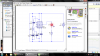
Add a 0.1uF ceramic or film capacitor and a 1uF electrolytic capacitor from pin 4 to pin 1 of the 555 with short leads. These capacitors are explained in the datasheet of the 555. Didn't you read the datasheet??
Are you soldering the circuit together properly or are you using a horrible intermittent solderless breadboard?
Are you soldering the circuit together properly or are you using a horrible intermittent solderless breadboard?