Continue to Site

Welcome to our site!

Electro Tech is an online community (with over 170,000 members) who enjoy talking about and building electronic circuits, projects and gadgets. To participate you need to register. Registration is free. Click here to register now.

  • Welcome to our site! Electro Tech is an online community (with over 170,000 members) who enjoy talking about and building electronic circuits, projects and gadgets. To participate you need to register. Registration is free. Click here to register now.

PLC potentiometer + resistor equations

Status
Not open for further replies.

PLC Nut

New Member
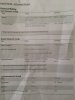
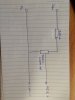
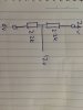
Hi, I am trying to supply my PLC input of my Easyio FG32 PLC with a simulated current of 4 - 20mA. Please see the attached pictures which include (PLC spec sheet, a voltage divider drawing and a potentiometer drawing)

I am having trouble figuring out the maths involved here. What I know already know is this:

My power supply outputs 24 VDC and cannot be trimmed to a lower voltage

Size the resistors:
R = V / I
= 24/0.02
= 1200 Ohm resistor

R = V / I
= 24/0.004
= 6000 Ohm
= 6000 - 1200
= 4800 Ohm potentiometer

My drawing shows a 5450 Ohm potentiometer because that is the only descent size one the shop had.

Power rating of resistors:
P = I2. R
= 0.02 x 0.02 x 1200
= 0.48 Watts (I have a 1 watt resistor as the shop has heaps of these)

P = I2.R
= 0.004 x 0.004 x 6650 (which comes from 5450 +1200)
= 0.10 Watts (I have a 1/4 watt rated pot)

Now the issue is that my PLC only accepts 0-10v DC @ 4 - 20mA. I have confirmed this with the manufacturer. Also I know that I can use the voltage divider to lower the voltage by half using two resistors of the same rating but that leaves me with 12V not 10V.

Questions:
  • What would the circuit look like to accomplish this? I am worried that if I use my potentiometer drawing that it will damage the input card of my PLC.
  • Can you please explain it better to me.
 

Attachments

  • IMG_0832.JPG
    IMG_0832.JPG
    354.2 KB · Views: 416
  • IMG_0841.JPG
    IMG_0841.JPG
    222.5 KB · Views: 902
  • IMG_0842.JPG
    IMG_0842.JPG
    218.8 KB · Views: 903
Hello PLC Nut.

The equations seem OK.

Why not using the series resistance and pot to get your 10V max input.
You can also create a sort of clipping circuit which clips the input voltage to ~ 10V if the input voltage tries to higher then 10V.
You could use a voltage divider (taking from the 24V, low imp. R divider) with a diode connected to the input.

Best of luck!
 
Thanks for your comments guys,

SneaKSz, could you please confirm the following using your idea of getting new gear from the shop.

24 - 14 = 10v

Size of Resistors:
10/0.02 = 500 Ohm Series Resistor

10/0.004 = 2500
2500 - 500 = 2000 Ohm Pot


Power:
P = 0.02 x 0.02 x 500
= 0.2 Watts = 1/4 Watt required

P = 0.004 x 0.004 x 2500
= 0.04 Watts 1/4 Watt required

The problem with this is that I can only find 1k and 5k pots.
 
Last edited:
There is no 4 in 0.

I see three types of outputs selected somehow.
1. 0-10 V out
2. 0 to 20 mA out
3. Open Collector output that sinks 0.3A

A LOT of stuff is missing from the specifications. For 2, there is sourcing and sinking and who supplies the power. See https://www.google.com/url?sa=t&rct...EXHiJQQNVCvOLtA&bvm=bv.93990622,d.eXY&cad=rja what I mean?

And I'll throw this https://www.google.com/url?sa=t&rct=j&q=&esrc=s&source=web&cd=1&ved=0CCkQFjAA&url=https://www.bapihvac.com/content/uploads/2010/07/understanding-4-20-ma-current_loops.pdf&ei=r2VhVZm6GMmhNsXtgfAD&usg=AFQjCNESEHRu7BHFJVQ8ZfnmNtX8s5Ht5Q&sig2=1fvJnXipi4PxE8jrF4okkQ&bvm=bv.93990622,d.eXY&cad=rja at you.
 
Last edited:
Hi Keepitsimplestupid,

You are right, it is missing a lot of stuff, and the manufacturer wasn't much help either. Basically I was thinking of either trying what is depicted in the picture below or I will lower the voltage even lower to 5v by changing the resistors and pot sizes to suit. What do you think?

1 - 5v Potentiometer.png
 
A 4-20mA receiver is usually(always?) a resistor across which the input current develops a voltage. That voltage is then converted by an ADC internally.
The ADC has a maximum-voltage-input spec that you do not know and likely cannot find out.

Best way is to make/buy an actual 4-20 source.
Some high-end DMM's contain 4-20 sources
 
I looked at outputs, not inputs, sorry. But, some comments are still valid.
Isolated, potential free, ground referenced etc.

I would ask them for a schematic of just the components connected to the real world for inputs and outputs. Usually, there is a compliance voltage that you can't exceed.

The reason why your dividers don't work out is probably because the input Z is not known and the compliance voltage is possibly larger than 10V. Usually to convert 0-20 mA to a voltage, you just put a resistor at the end of the line, so it may be much easier to use the 0-10 V inputs.

Figuring out the input Z of voltage inputs is easy. Put a high value pot in series with a 10 V source and adjust for 5V in. (1/2 Vin initial) Take pot out of circuit and measure the pot. That's the input Z.

So assume the voltage can't be more than 10 V at 20 mA or at 20 mA, the voltage read across the internal resistor is 10V.

I agree with Wade.

Simulate with a voltage source in parallel with a resistor, but this has input Z problems.

The pot trick works for voltage, but it might work for current only if you used a zero resistance ammeter.

Usually, I would expect the inputs to be 0-5V for 0-20 mA with a max allowed open circuit voltage of 24 V or so.

I looked at some of the docs and it's mostly a sell sheet and a sucky one at that.

In systems I put together, current output was used to set a voltage at the input of a device with the resistor at the device and the voltage was read at the device differentially. You really have to pay attention to ground loops.

The LM334 and The LT3092 are two possible simple parts to use. 4-20 mA simulators/calibrators also exist.

In your calcs you not taking into account the input Z. These are not ideal voltage sources (Z=0) and not ideal current sources (Z=infinity) and they are not zero resistance ammeters (feedback ammeters( with a voltage drop < 1 mV).

The current input may look like a 500 ohm resistor. e.g. 10/20e-3.

BTW: KISS works.
 
Last edited:
Thanks guys for your input on this (pun intended). What I havent told you is that I'm away at the moment and havent had the chance to phyically play with all the parts and my meter yet.

I will get back to you with an outcome shortly :)

Cheers
 
Wade:

Exactly.
I said:
Usually, I would expect the inputs to be 0-5V for 0-20 mA with a max allowed open circuit voltage of 24 V or so.

Interfacing to power supplies turned out to be a real PITA because the programming voltage is referenced to the +output and the output was referenced to ground.
 
Status
Not open for further replies.

Latest threads

Back
Top