Continue to Site

Welcome to our site!

Electro Tech is an online community (with over 170,000 members) who enjoy talking about and building electronic circuits, projects and gadgets. To participate you need to register. Registration is free. Click here to register now.

  • Welcome to our site! Electro Tech is an online community (with over 170,000 members) who enjoy talking about and building electronic circuits, projects and gadgets. To participate you need to register. Registration is free. Click here to register now.

Plasma Speaker

Status
Not open for further replies.

Menticol

Active Member
EDIT: I'm sorry! I didn't checked this thing completely before posting it, this circuit is... well, it works, but it's still crap. I'm looking for a decent replacement right now.

Hello!

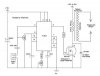
Here is another contribution, check the attachments. I know it was already posted somewhere in the forum, and this particular circuit is quite inneficient.

But finally there is a right place to discuss it.

A video
www.metacafe.com/fplayer/1963063/plasma_speaker_early_prototype.swf

The Site
**broken link removed**

Warning: 47 nf 2Kv is wrong. It's 47 uF
 

Attachments

  • FSNTLXVFMMD1ALS.MEDIUM.jpg
    FSNTLXVFMMD1ALS.MEDIUM.jpg
    15.7 KB · Views: 4,790
Last edited:
I made it 2 or 3 years ago for somebody.
The output sound is not so good but it does work. besides it seems to work as a tweeter (so just good for high frequencies).
 
there's two different types of this device. the first is a single sharp point and the corona discharge around it is what produces sound, the second requires more current, but is more efficient, and is a device using a spark gap. i have made both types at one time or another. the spark gap type also seems to have a better frequency response, probably because it's coupling mode to air is a thermal effect rather than just ionization/dissociation. here in the US, it's most commonly called an IONOPHONE.


the first pic is a corona discharge model of ionophone, the second one is an arc type (and yes the electrodes are a bit hot). one of the best transformers to use for making an ionophone is an old-style flyback transformer. the newer FBTs have internal rectifiers and capacitors, and their output is DC. you want one that can produce high frequency AC, and they're not as common as they used to be. if you can find an old 1960's or 70's color TV that used a high voltage rectifier that was external to the flyback, that's the type of flyback that's best for an ionophone. you can find high frequency self oscillating driver circuits in a lot of "experimenter's collections" of circuits in books. all it takes is usually a couple of power transistors, a couple of diodes and some resistors. you wind two center tapped windings on the FBT core, one for the base drive, and the other forms the collector load (this one should be at least 18 guage wire). usually the assembly notes in the circuit will tell you how many turns each winding is. if it doesn't oscillate the first time, swap the base connections on the transistors, as many circuit diagrams for these oscillator circuits have typographical errors (or you just have the base connections reversed to begin with)

once you get one running, you can add an audio transformer inline with the power supply, and modulate the power supply voltage with audio.
 

Attachments

  • plasma.jpg
    plasma.jpg
    23.5 KB · Views: 1,106
  • iml_open_small.jpg
    iml_open_small.jpg
    27.1 KB · Views: 1,007
Last edited:
Why play with a dangerous, distorted, poor frequency response toy?
Why not use a good dynamic tweeter instead?
 
actually the Electro-Voice tweeter had very little distortion as long as it was operated within it's input voltage limits, plus it was completely enclosed, so it presented no safety hazards. the two tweeters shown are operated inside grounded cages.

dome tweeters distort at least as much as an ionophone, and their frequency response isn't pretty either, mostly because of mechanical limitations.

where i work, we sometimes get electrostatic speakers (a completly different animal than an ionophone, but does use a high voltage element) in for repair, and the screens on them are at ground potential with no audio, but carry high voltage peaks when audio is applied. they are sold as consumer audio, but you don't want to touch one with audio applied. the real high voltage element is the film between the plates (3kv), but it isn't exposed anywhere. if he power supply is removed, there's enough charge stored on the film that the speaker keeps on working for a couple of minutes.

why use an ionophone? 1) it is a VERY INTERESTING device with no moving parts. 2) if constructed properly it can exhibit very low distortion and a very flat frequency response.

in the type of ionophone, the frequency response is determined by the length of the spark. i was reading a while back that a firefighter got interested in ionophones after seeing a forest fire that got under high tension lines (flames are composed of ionized gases) and hearing a 60hz rumble (from several miles away) as the 60hz high voltage modulated the flames (i'd hate to guess just how much current was passing through the flames).
 
Last edited:
Many high quality and high fidelity tweeters are dynamic and work extremely well.
Very few plazma speakers are used.
I wonder why?????????????????????????????????????????????????
 
The best tweeters I have ever heard are the EMIT tweeters from Infinity. They're the only ones that really are almost omni directional and do not drop off as you move off axis. They also don't have any of the tinny sound effects of horns. First time I heard them my jaw dropped and I have been listening to Infinty Qc ever since. Not sure if they still make the EMIT tweeters but they are great. These are the ones:
 

Attachments

  • EMIT.jpg
    EMIT.jpg
    33.5 KB · Views: 869
Last edited:
Well, everything in audio is relative. The best equipment sounds horrible on some spaces, or with some specific tunes. A horrible equipment may sound great with a specific track and some luck. Ignorant people will call "best" the worst equipment, and vice versa.

AAghhh!! I Give up! Never ends...

Here is a little selection of the worst audio related - technical and aesthetical crimes I've found

PS: By the way, does anyone have a decent plasma speaker schematic for this thread?
 

Attachments

  • IMG_97801.jpg
    IMG_97801.jpg
    39 KB · Views: 856
  • car1.jpg
    car1.jpg
    28.2 KB · Views: 1,812
  • 2rmvcl2.jpg
    2rmvcl2.jpg
    46.1 KB · Views: 763
  • m_sound.jpg
    m_sound.jpg
    36.2 KB · Views: 3,070
  • 2155321975_350078ef52.jpg
    2155321975_350078ef52.jpg
    202.2 KB · Views: 1,110
Last edited:
i'll see if i can find one. i'll warn you, 90% of the schematics out there are tube circuits, so i'll try to find one of each, tube and solid state...

btw... at least those 18" woofers in the red pickup truck can really be classified as subwoofers. my personal opinion is somewhat old-school, it's not really a woofer if it's 10" or less diameter, just because of the air mass that has to be moved at lower frequencies. a lot of the "subwoofers" i see these days don't move enough air to be very efficient, and a lot of them suffer from their own cancellation effects because of the physical size of their box. i know someone where i work that used to own several of the newer small sub boxes at home. he began working with a band, and got a chance to hear some real bass bins. he soon sold all of his box subs and bought a pair of used JBL twin 15" PA bass bins, and has been hooked on them ever since...
 
Last edited:
A solid state amplifier has a very low output impedance that damps the resonances of a speaker very well.
A vacuum tube amplifier does not damp a speaker because its output transformer is a fairly high impedance so the speaker "booms" at resonance. Some speakers and some people like a boomy bass.
 
a lot of the class D amps also have a high output impedance because of the lack of a feedback loop. it is rather difficult to provide feedback in a class D amp (it can be done but it isn't as simple as with class A and B amps). i have seen tube amps with some feedback, which does reduce the output impedance below the impedance of the transformer, but usually not by much. an interesting tube design is the "circlotron" which uses two floating power supplies, and drives the output transformer from the cathodes. there was an electro-voice amplifier that used this method, and actually had a control in the feedback loop that could adjust the output impedance down to about an ohm or so. solid state amps, because of their very large open loop gain and very effective feedback, often have output impedances of about a milliohm. some Crown PA amps have output impedances of a few tenths of a milliohm (Damping Factors of anywhere from 5,000 to 10,000). of course, adding the resistance of the speaker wires increases the output impedance to the amp plus the speaker wires.

for anybody that thinks AudioGuru and i just took the discussion "into the ozone" (pardon the pun), the output impedance of an amplifier determines how the amplifier and the speaker interact with each other. speakers are actually a linear magnetic motor. magnetic motors produce a "back EMF" when the coil moves through the magnetic field. to see this effect with a speaker, connect a voltmeter to the speaker terminals and tap on the speaker cone. you will see the meter read some voltage. this is the back EMF a speaker produces. when you play music, the cone moves. the cone has mass, so it has inertia. when the amplifier changes the current through a speaker, the cone moves to duplicate the change in the form of motion. since the cone has mass, the cone doesn't follow the current instantaneously, and the inertia produces an opposing voltage at the terminals of the speaker (this is an oversimplified description, there's really a LOT going on here....). this back EMF can actually cause the speaker to "do it's own thing" and not follow the amplifier as intended.... now back to a physical demonstration for a second. while you are tapping on the speaker cone, place a short across the terminals of the driver itself. you hear the motion dampen (this demonstration works best with a subwoofer with very loose suspension) and the sound of your tapping changes. this is because the back EMF is driving a short circuit and produces a braking effect in the magnetic field around the voice coil (the same effect happens with a DC motor when you short the motor wires and try to turn the shaft). this is what a low output impedance in an amplifier does, and in effect allows the feedback loop in the amplifier to exert a certain amount of control over the cone motion. the lower the output impedance, the more accurately the cone follows the amplifier. how the feedback lowers the output impedance, is that any voltage that shows up on the output terminals, that is not present at the input (whether it's distortion produced by the amplifier or back EMF from the speaker) gets fed back to the input and compared against the input signal. if it's different, the amplifier corrects it. this feedback effect can by this correcting action lower the output impedance far below the actual output resistance of the amplifier. in other words, (and i've actually done this experiment) if we took the speaker output terminal, and placed a 10 ohm resistor in series with the output, that will increase the output impedance by 10 ohms. if we then move the feedback "tap" from the speaker line of the amp board to the speaker side of the 10 ohm resistor, the output impedance will drop back down to far below 10 ohms. the amplifier will do whatever it must to keep the feedback and the input signal equal. of course with the 10 ohms "internal" resistance, the overall gain of the amp remains the same, but the level that the amp clips at is reduced, because the amplifier is working harder to produce the same voltage at the feedback "tap". the actual output of the amplifier is still being driven rail to rail, but the voltage drops across the "internal" resistor as it forms a voltage divider with the load.
 
Last edited:
I am not "into the ozone". I just like reproduced sound to be as much like live sound as possible. Very low distortion, very low noise, very wide bandwidth and good transient response.

The extremely low output impedance of a modern amplifier damps the resonances of a speaker properly to make a good transient response. Then the speaker sounds "tight" and produces many frequencies instead of boomy like a one-note bongo drum.
 
"I am not "into the ozone"."

sorry i didn't mean it like you took it, i was just saying that when we went into the subject of output impedance and damping factor, we probably were discussing something that was far beyond the experience of most of the people on this board. that's what i meant by "into the ozone" (plus it was also a pun on the original topic which i couldn't resist...). i agree wholeheartedly about how an amplifier and speakers should sound. i like amps with high damping factors as well, and actually have a design i'm working on with a variable damping factor (yes there are people who like the sound of low damping factor amps).
 
Hi Uncle Jed,
Of course I know what you mean.

Most NOOBs don't know (or care) about high fidelity and maybe have tin ears.

I am an old geezer but my hearing is still excellent because I took care of it.
I studied music and have always liked to hear good music (not acid rock noises).
 
Hi Jed,

Thank you for the excellent description of the effects of a low impedance drive to the speakers.
Just cos i know about it, doesn't mean i can explain it to others.

Now i can point to your post about it.

John :)
 
i'm trying to keep what hearing i have left... i used to play bass in rock bands, and the big "occupational hazard" there was the fact that i stood next to the drummer, with a ride cymbal right next to my head... so my right ear has a bit of hearing loss above 10khz. after i began noticing the hearing loss, i began wearing earplugs when we played.


getting back to the original topic, i did find schematics of a tube based ionophone, still looking for a transistor version, which if i can't find it, i'll draw up one i've used in the past. there ARE a few commercially made ionophones out there, but they are usually very expensive, because they are usually hand made or use specialized components (like the RF transformers that create the spark). there's a frequency response graph here, which to a newbie may look awful, but if you look at the response graph for most speaker system tweeters, it's actually comparable to a lot of electromechanical tweeters. the low frequency rolloff is actually determined by the RF rest votage of the tweeter. the higher the voltage, the lower the cutoff frequency, because a larger volume of air is ionized. the linearity of the modulator determines the distortion. so if an ionophone sounds distorted, the modulator isn't operating linearly.
 

Attachments

  • Plasma_Mod_new.gif
    Plasma_Mod_new.gif
    13.8 KB · Views: 3,380
  • Plasma_RF_new.GIF
    Plasma_RF_new.GIF
    13 KB · Views: 2,471
  • freq.gif
    freq.gif
    44.8 KB · Views: 903
One of my old buddies had a super expensive subwoofer that had a "monitor loop" winding on the voice coil to measure the speaker's actual physical position and compare it to what he amplifier was telling it to do. This was fed back to the amplifier and supposedly controlled the speaker better. Sounded pretty good.
 
Yeah, it's a separate few turns of wire wrapped around the voice coil but electrically separate. Sensing the voltage across those leads gives you good feedback to the actual position of the cone. Pretty much the same theory as the feedback coil from a flyback transformer.
 
Last edited:
I thought the whole point of the High Voltage section was just for making unique and interesting high voltage based stuff. ;)

I didn't know that all high voltage projects need to be high fidelity devices for them to be acceptable projects for others to build.:confused:
 
Status
Not open for further replies.

Latest threads

New Articles From Microcontroller Tips

Back
Top