Electro Tech is an online community (with over 170,000 members) who enjoy talking about and building electronic circuits, projects and gadgets. To participate you need to register. Registration is free. Click here to register now.
Welcome to our site! Electro Tech is an online community (with over 170,000 members) who enjoy talking about and building electronic circuits, projects and gadgets. To participate you need to register. Registration is free. Click here to register now.
Now on the circuit board (with the transformer removed)............... there is a resistance of about 10 ohms between Terminal 1 and Terminal 2 (primary side) because of the thicker wire link.
Hi John,
Measuring the resistance between secondary points 1 and 2 on the circuit board with the transformer removed should read infinity. Point 2 only goes to a short piece of track that is not connected to anything else. It would only be connected if the unit was configured for 220 volts. If that was the case the short link would be fitted and the longer link removed. With all the cables still connected to the board can you measure the resistnce between points 1 and 2 on the secondary side. These finish up being connected to the filaments on the display.
Correct...........now that I understand it is one or the other.......it makes sense. (Either 240vAc or 220vAc). Interestingly the short link must have been cut (when assembled), because there is a link soldered in there.
With all the cables still connected to the board can you measure the resistnce between points 1 and 2 on the secondary side. These finish up being connected to the filaments on the display.
Have just been and measured the resistance on the board across points 1 and 2 on the circuit board : Unfortunately it is open circuit, infinite resistance.
Does this mean that the filaments on the display have all blown ?
Hi John,
It looks that way assuming that ALL of the interconnecing cables between boards are still connected. It thik there are two (Possibly more.) dispalys. I can see what looks like two bar graph displays on the schematic. You will know better as you have seen the unit. Before deciding they are definitely faulty I suggest measuring directly across the filament pins on the dispalys.
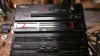
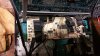
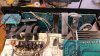
I have been and tried.............but I just do not know where to start.......It is a complex piece of kit with boards and wires everywhere. Cannot get to the displays.
Please see photos
I am delighted to be able to tell you that a friend of mine gave me a transformer which has output voltages fairly close to those of the original on my Pioneer Hifi.
He established from the service manual that the original transformer had the following characteristics :
Original transformer
Input voltage (Primary) : 240v AC
Output voltages (secondary) : 3v AC, 30v Ac, 14v AC
The replacement transformer :
Input voltage (Primary) : 240v AC
Output voltages (secondary) : 3.6v AC, 36v Ac, 9.2v AC
(This transformer is much larger in size than the original, so I was not worried about the wattage output)
Anyway I decided the voltages were close enough............so wired it up, and it all works !
This site uses cookies to help personalise content, tailor your experience and to keep you logged in if you register.
By continuing to use this site, you are consenting to our use of cookies.