Continue to Site

Welcome to our site!

Electro Tech is an online community (with over 170,000 members) who enjoy talking about and building electronic circuits, projects and gadgets. To participate you need to register. Registration is free. Click here to register now.

  • Welcome to our site! Electro Tech is an online community (with over 170,000 members) who enjoy talking about and building electronic circuits, projects and gadgets. To participate you need to register. Registration is free. Click here to register now.

PIC plus-5110 LCD-GPS-BMP280-HMC5983

Status
Not open for further replies.
It's just a loaded program as a graphic demonstration of the 5110 library, the clock at the end is driven by a simple routine I wrote for the demo - it generates a random hour, minute, and second, then it's driven by timer interrupts at one second intervals. I have also had it running using the same hardware from a DS3231 I2C clock module - a similar one second interrupt, but generated by the DS3231, was used to update the clock display.

This is the sine wave part:

Code:
    Nokia_ClrScr();
    Nokia_DrawRect(0, 0, 83, 47);
    Nokia_DrawLine(0, 23, 84, 23);
    Nokia_DrawLine(41, 0, 41, 47);
    for (c = 0; c < 4; c++) {
        for (i = 0; i < 84; i++) {
            y = i * 0.017453292519943295769236907684886;
            Nokia_InvPixel(i, (sin(y * 6)*20) + 23);
            Nokia_Update();
            Delay_ms(20);
        }
    }

I know it's in C, but it's simple to understand - the first four lines clear the screen, and draw the background.

'for (c=' runs the routine four times, and 'for (i+' draws the 84 dots across the screen.

InvPixel inverts a pixel in the buffer (you can't do it on the screen, as it's read only), Update transfers the buffer to the screen.

I've no idea what the scaling value 0.017453292519943295769236907684886 is all about?, it was in the routine when I downloaded the Arduino version.
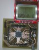
The scaling value is angle of one degree in radians.
 
hi C,
You may find this program of interest, give it a run.
E
Hi E,
There was nothing wrong with my 18LF2520 I retried your 'scrolling' program, and it works fine (So the PIC has enough memory).
Excellent stuff, I can visualise many uses for it, as it makes a small screen larger.
Thanks.
C.
 
Hi,
I am changing PICs fro 18LF2520 to 18LF4520, because while redrawing the Schematic I realise that I will have to start again if I run out of PINs.

NOTE: from now on all of the PIN outs will be different from above examples!
C.
 
Hi,
Here is the 18LF4520 Schematic, with 5110, GPS,SX1278 radio module, and Barometer.
Please check for errors.
EDIT: I found errors so I will try again.
C
 

Attachments

  • 18lf4520 TEST PCB.gif
    18lf4520 TEST PCB.gif
    44.2 KB · Views: 219
Last edited:
Hi E,
I am testing the scrolling program on my latest PCB, with 5110 screen.
The program is looking for the font1 with big2lcd inside, can you point to it please, while I search.

EDIT: I found the big2lcd font1 at #145. I'm not sure if it is the scrolling program, but it compiles.

C.
 
Last edited:
Hi,
I've moved Eric's scrolling/large text program from 18LF2520 (which works) onto 18LF4520, but I can't get the screen to work.
Here is the program and a digital scan. (PIN 4=RST and PIN5=D/C)
Any ideas, please?
C
 

Attachments

  • 18f2520 8MHz SCROLLING TEXT SPI SCK TEST 041217.txt
    8 KB · Views: 200
  • SPI.jpg
    SPI.jpg
    151.7 KB · Views: 194
In the program reset is in PortC Pin1 and D/C Pin0.
PortC Pin0 is input.
Hi J,
This is true, here's the Schematic.
If I'm correct, are you referring to the digital scan not having the same settings? In which case, it has it's own settings, I just connect them according to each test. (Or am I misunderstanding what you mean?)
Thanks.
C.
 

Attachments

  • SCH.jpg
    SCH.jpg
    196.3 KB · Views: 197
Hi,
The CS on RD4 wasn't working.
After lots of digital tests, I looked at DATA sheet and found reference to RD4 and a NOTE at the bottom, which showed that for RD4 to be output, it needs setting with LATD no PORTD, which I changed and it now shows working. (the screen is still not working) I've never used LAT before!
I'll look again tomorrow.
(Note the program on #188 is wrongly named 18LF2520, it should read 18LF4520)
C.
 
Last edited:
Hi J,
This is true, here's the Schematic.
If I'm correct, are you referring to the digital scan not having the same settings? In which case, it has it's own settings, I just connect them according to each test. (Or am I misunderstanding what you mean?)
Thanks.
C.
I mean, if you are using the program #188, then the pins in the text in #188 don't fit with the pins in the program.
I did not check the schematic.

Edit: I did not notice, that you were referring the analyzer pins.

Anyway in the program you have TRISC= %00000001 so PORTC.0 =D/C is an input pin but it should be output.
 
Last edited:
I mean, if you are using the program #188, then the pins in the text in #188 don't fit with the pins in the program.
I did not check the schematic.

Edit: I did not notice, that you were referring the analyzer pins.

Anyway in the program you have TRISC= %00000001 so PORTC.0 =D/C is an input pin but it should be output.
 
Hi J,
Hurray! Got it going.
I've corrected as many mistakes as I can, here is the program:
Thanks for the help.
C.
I mean, if you are using the program #188, then the pins in the text in #188 don't fit with the pins in the program.
I did not check the schematic.

Edit: I did not notice, that you were referring the analyzer pins.

Anyway in the program you have TRISC= %00000001 so PORTC.0 =D/C is an input pin but it should be output.
 

Attachments

  • 18f4520 8MHz SCROLLING TEXT 5110 SPI 051217 1100.txt
    8.2 KB · Views: 207
Hi,
I notice that the 5110 screen varies between having a white screen with black letters, ok, to a black background. I also saw with another screen where there were lots of pixels all over the screen, but I did get that screen hot on one occassion.
Here's an image of the screen, any ideas.
I've got to the stage where I can at last look deeper into Eric's program, to understand it better.
C.
 

Attachments

  • PCB and 5110.jpg
    PCB and 5110.jpg
    199.1 KB · Views: 217
Hi,
I notice that the 5110 screen varies between having a white screen with black letter, ok, to a black background. I also saw with another screen where there were lots of pixels all over the screen, but I did get that screen hot on one occassion.
Here's an image of the screen, any ideas.
I've got to the stage where I can at last look deeper into Eric's program, to understand it better.
C.
The settings are wrong, basically the contrast is too high, although there are a couple of other settings that give a similar effect.
Hi N,
I found the contrast comment in the program :) and now it has good contrast.
Thanks C.
 
Hi,
Today it was poor again, I tried different settings, but couldn't correct it.
I had read that sometimes the screens need bedding down, because of the 'rubber' contact strip not being seated. I found that if the frame and PCB are squeezed, then the rear tabs tightened, it has cure it.
C
 
Last edited:
hi C,
It is a common fault with LCD's, flexi-cable cable pressure contacts.
Twist the rear metal tabs VERY carefully so that more pressure is applied along the contacts.

You can easily modify your programs to use the hardware SPI in Oshonsoft Basic rather than the software version, much faster.
E
BTW:
Now have the 9225 2.2inch TFT fully working using Oshonsoft Basic.
If I can make a decent video, I will post to you tube.
Using the 18F4520, 20MHZ xtal and the internal *4 PLL, the PIC is running at 80MHz, so the SPI clk is 20MHz.
 
Status
Not open for further replies.

Latest threads

New Articles From Microcontroller Tips

Back
Top