Continue to Site

Welcome to our site!

Electro Tech is an online community (with over 170,000 members) who enjoy talking about and building electronic circuits, projects and gadgets. To participate you need to register. Registration is free. Click here to register now.

  • Welcome to our site! Electro Tech is an online community (with over 170,000 members) who enjoy talking about and building electronic circuits, projects and gadgets. To participate you need to register. Registration is free. Click here to register now.

PIC resets when MOSFET is driving inductive load

Status
Not open for further replies.

Futterama

Member
Hi,

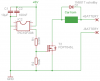
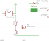
I have this 12V car horn I would like to drive using a PIC. I have made a simple circuit using an external 12V battery for the car horn supply. I'm using a MOSFET for driving the horn. But when the PIC turns on the MOSFET, the horn just makes a small "click" and the PIC resets. If I disconnect the MOSFET gate from the PIC pin and activates the MOSFET manually by connecting the gate to VDD through the 220R resistor, the horn sounds but the PIC still resets (I use a LED from another PIC pin to see if my PIC program starts over).

I suspect the inductive back EMF or similar from the horn is causing the reset. I just don't know how to avoid this. I have tried placing some schottky diodes, but this didn't help, maybe I didn't place them correctly?

The car horn is a solenoid and when current runs through, it pulls on the sound membrane. This pull also disconnects internal contacts inside the horn and the solenoid is disconnected from the supply. The sound membrane then pulls back and connects the solenoid again, repeating the process. You probably know this principle and there is maybe even a name for it that I don't know of ;-)
 

Attachments

  • test_schematic.png
    test_schematic.png
    6.5 KB · Views: 521
Oh, I forgot to mention that the 5V to the PIC is from another 5V battery not related to the 12V battery.
 
The easy solution would of course be to use a relay, but they get pretty big if they should be able to handle 5V for the coil and 3-4 amps for the horn.

Another solution I was thinking of, was to use an optocoupler and let the PIC drive the emitting diode and let the phototransistor activate the MOSFET.
 
Does the PIC have a reset pin? left floating.
Keep all wires short in the PIC area.
Add capacitors on the +5V to ground.
 
MCLR reset is disabled using the fuses and the pin is used as digital input.
I actually have a 10µF cap between GND and +5V, just forgot to put it in the schematic.

I have tested a breadboard circuit where I use an optocoupler between the PIC and a N-channel MOSFET, it seems to work well.

The original circuit was already on a PCB and worked very well with high-current bulbs and also with a modified horn where I removed the internal contacts and just pulsed the MOSFET, it worked even without schottky diodes.
 
Tie both grounds to the same spot(lug). Use short wires to connect,particularly on the grounds. Put a spike diode(5volt zener) with cathode to pin 4 and anode to ground.
 
BeerBelly, why do you assume a spike diode is needed on pin 4? If I disconnect pin 4 and connect R3 to VDD, the MOSFET turn on and the PIC still resets but ONLY when it's the horn that's connected, it does not reset if I replace the horn with a 12V headlight bulb.
 
MCLR reset is disabled using the fuses and the pin is used as digital input.
I actually have a 10µF cap between GND and +5V, just forgot to put it in the schematic.

I have tested a breadboard circuit where I use an optocoupler between the PIC and a N-channel MOSFET, it seems to work well.

The original circuit was already on a PCB and worked very well with high-current bulbs and also with a modified horn where I removed the internal contacts and just pulsed the MOSFET, it worked even without schottky diodes.

Not good enough - you really need a couple of 0.1uf (100nF) ceramic decoupling capacitors as close to the PIC pins as possible. Maybe even consider a couple of 1uf ceramic and 10nF in parallel just to be on the safe side. Car electronic equipment picks up a shedload of bad noise at the best of times.
 
Also consider putting a fuse in series with the mosfet to the horn/relay as if someone reverse connects the battery you will find lots of smoke coming from your circuit.
 
This circuit now works on breadboard with short wires. The 10µF is an electrolytic capacitor and the 100nF is a polyester capacitor. I don't know, this doesn't seem different from what I started with, except the 100nF but it even works without it. Damn I hate this :confused: I'm sure the circuit won't work tomorrow :p
 

Attachments

  • schematic.png
    schematic.png
    7.3 KB · Views: 421
If it's any consolation, I spent a month chasing an issue with a product which actually turned out to be two seperate issues - an undocumented interrupt issue plus a decoupling issue.

I've never made the decoupling error again .....
 
I have just discovered that it makes a difference how I connect the polarities on the horn though there is no polarity indications on the horn. But if I connect them one way, I have no reset problems, or they are at least very infrequent, if I switch the wires on the horn terminals, I get the reset problem again.

There must be a difference in which polarity is disconnected internally by the contacts.
 
BeerBelly, why do you assume a spike diode is needed on pin 4? If I disconnect pin 4 and connect R3 to VDD, the MOSFET turn on and the PIC still resets but ONLY when it's the horn that's connected, it does not reset if I replace the horn with a 12V headlight bulb.
Are you telling me the only thing in common between the PIC and the horn is the ground?
My thought was possibly that the capacitive coupling between the source/gate was sending a spike to pin 4.
 
Are you telling me the only thing in common between the PIC and the horn is the ground?
Yes, and I don't see how the PIC can be affected then, but it does somehow. Can a spike from the horn be so powerful it induces another spike in nearby wires?
 
How do you know the PIC is being reset, Do you have a meter or LED indicator hooked up telling you this? Is the 5 volts on it's own battery?
 
I have a LED blinking at startup before horn activation. Yes, 5V is from another source, not battery actually, but from my PICkit2.
 
I have a LED blinking at startup before horn activation. Yes, 5V is from another source, not battery actually, but from my PICkit2.

Ah ha, have you considered that the PK2 may not have enough current capability for your circuit? If you search the Microchip forums, you will find comments to that effect, which also applies to the PK3.

A simple test would be to use a more robust 5-V supply to the circuit and see if the problem persists.

John
 
Yeah, I also tried my 20A lab supply with same result. As far as I can remember, the PICkit2 kan deliver around 100mA and my circuit is really only a PIC, a lowpower LED and the MOSFET. The current peak into the MOSFET gate is limited by the 220R resistor (22mA). So the PICkit2 should be just as fine as the lab supply.
 
You may find that swapping the polyester for ceramic will fix the problem. Decoupling is one of the main causes of problems on this forum.

Mike.
 
Status
Not open for further replies.

Latest threads

New Articles From Microcontroller Tips

Back
Top