Continue to Site

Welcome to our site!

Electro Tech is an online community (with over 170,000 members) who enjoy talking about and building electronic circuits, projects and gadgets. To participate you need to register. Registration is free. Click here to register now.

  • Welcome to our site! Electro Tech is an online community (with over 170,000 members) who enjoy talking about and building electronic circuits, projects and gadgets. To participate you need to register. Registration is free. Click here to register now.

PIC based high-resolution cap meter

Status
Not open for further replies.
OK, sorry for the delay Wjhos but I finally worked out what you meant. :)

Originally the capmeter code was only JUST squeezed into a 2k PIC, so I left out the nicety of leading zero correction. It was a trade-off to still be able to fit all that 32bit math code into a tiny cheap PIC.

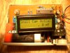
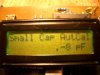
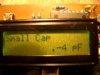
So in the original HEX file it shows; " . 1pF" and " .-3pF" instead of "0.01pF" and "-0.03pF".

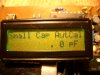
However there are probably other fussy (OCD?) people like yourself that really hate imperfect leading zeros. ;) So I found a way to squeeze the leading zero correction into the code.

I have re-programmed my own Capmeter and it seems to be all working perfect, and since this was only a minor display tweak I have not bothered with keeping the old HEX file, so the one on the web page is now the new improved HEX.

And thanks for the suggestion. :)

New HEX file is here;
https://romanblack.com/onesec/CapMeter.htm
 
Hello,

I read your answer, and it is exactly what i ment. As you asked for some fotos, i was making them just before reading the answer. I have attached them and they show the problem, which can now be solved using the new hex file, which i will download and flash shortly. Sorry, the fotos are not that sharp, but i used a simple camera. I can also post the PCB layout (which is in Sprint 5.0 format)

thanks for your esponse
 

Attachments

  • CIMG0298.JPG
    CIMG0298.JPG
    632.9 KB · Views: 584
  • CIMG0297.JPG
    CIMG0297.JPG
    623.5 KB · Views: 502
  • CIMG0295.JPG
    CIMG0295.JPG
    611.1 KB · Views: 447
  • CIMG0294.JPG
    CIMG0294.JPG
    625.3 KB · Views: 457
Hello,

For some reason, the download hex file does not work. I do not remember how i did it the first time, but i think i had to copy/paste the file to wordpad. I did that now too, but when i load the file to my Pickit2, it is not completely the same. In the meter it does nothing at all. Can you provide the file as a downloadable file that can be directly imported to a programmer. It seems now it is a hypertext file ?.

regards
 
Thanks for posting the photos that looks like a nice neat tool you have built there! :)

And I like your old grainy reflector supertwist LCD, they have great visibility and with no backlight they only use a couple of mA. Those old LCDs are getting hard to find now, all the LCDs now have backlights and use 20-40mA. :(

Re the HEX file, the link I provided above is to the project web page. The link directly to the HEX file is here;
https://www.romanblack.com/onesec/CapMeter.hex

Re your PCB layout, sure if you like you can post it here. It may be of interest to people who want to build their own PCB. :)
 
After finishing the capmeter, i tested a mylar cap, 10uF, which had been on my workbench for a very long time. It appeared to be still charged to some extend, so it blew the input of the capmeter and i had to install a new PIC. Therefore i added a 4.7v zener across the input and a 100 ohm series resistance to give some protection. The meter seems to work properly, altough the initial displayed cap value has gone up to about 390 pF. ( was 325 pF )
Does it realy influence the accuracy of the meter ? And is there maybe a better and more elegant way to protect the input against accidentaly charged capacitors ?
I attached the layout of my PCB, without the protection components. It is in Sprint format. A free viewer can be found at abacom.de
 

Attachments

  • capmeter.GIF
    capmeter.GIF
    21.6 KB · Views: 701
Last edited:
How long had the cap been on the bench "charged"? That sounds pretty unusual, it's more likely the PIC was damaged due to a wiring short etc.

The PIC input pin is already protected to some extent by its internal pin diodes, these are good for 20mA continuous and a couple hundred mA for short term one-off events. I don;t think a 10uF cap charged at 5v has enough energy to blow the PIC pin diodes. Maybe if your 10uF cap had been charged to a higher voltage it could do it.

You can add a zener if you like, and the increased initial capacitance is just because the zener adds a bit of capacitance, as you measured about 65pF. That should zero out normally when you press the zero button.

The 100 ohm resistor in series with the RA0 pin is also fine and should not really affect the operation of the meter, and you could even to go 330 ohms there for more safety.

Personally I'm in the habit of shorting cap leads to discharge them before measuring IF they have been in a breadboard etc and may have some charge left in the cap.

And if your 10uF Mylar cap was a high voltage type, that you know had been connected to a high voltage, that's a perfect example of WHY why you short out cap leads before measuring, even if the capmeter does have added protection! ;)
 
You can add a zener if you like, and the increased initial capacitance is just because the zener adds a bit of capacitance, as you measured about 65pF. That should zero out normally when you press the zero button.

How about a TVS diode (or "transorb")? They are low leakage, low capacitance and can withstand fairly large transients for a short time.

You'd still need to discharge large capacitors, but a 5V TVS diode might offer better characteristics than a regular zener.
 
Sure a transorb would be better still for protection. But I would worry a bit about it behaving differently at different frequencies, especially if it's a 5v limiting device in a 5v oscillator.

The idea of the cap meter is that it's pretty good at measuring small caps right down to fractions of a pF so it would be a shame if a "safety" modification somehow upsets the performance. A resistor on that RA0 pin is the simplest safety mod and least likely to affect the performance.

Regarding the safety a lot of people have built these on their own PCB or from the internet kit and PIC failures are very rare.
 
need a bit of help in programming the pic please

need a bit of help in programming the pic please.
i am using mikroelektronika's EasyPic 4 board..
PIC16F628A chip with 16Mhz Crystal..
everything the same as your version..
your new version of hex..
 

Attachments

  • Capture.PNG
    Capture.PNG
    130.5 KB · Views: 475
Hi PaulCo, your configs are not correct. I just loaded the Capmeter.hex into my MikroFlash programmer, and the configs read correctly;

osc = hs
wtchdog = off
power up timer = on *
master clear = off
brownout = off
low voltage program (LVP) = off *
data ee protect = off

Yours is different in 2 * places.

I think it could be the EasyPIC 4 hardware forcing the PIC into LVP mode by holding the PORTB pin high.

Try this;
1. on the EasyPIC4 set the PORTB pullup jumper (right hand side of pcb) to PULL DOWN (that stops LVP being activated)
2. open a new PICFlash on screen
3. select PIC 16F628A
4. file -> load HEX -> Capmeter.hex (configs should be correct to match mine)
5. click "Write" button to program the PIC
6. check the configs are still shown correct, and there were no error messages
7. yay! success. :)
 
for some reason just cannot get it going (still working on it)..

for some reason just cannot get it going (still working on it)..
so i made a different version with same components and it worked, just not as precise as your one..
so means that the components can be ruled out.. this makes me think it's PIC16F628(A)
ordered some PIC16F628 & 270p 1%
will let you know how i get on..
 
Last edited:
Is it on breadboard? Do you have a photo? That will help a lot to see if there is an issue with the construction.

I don't think the 628 or 628A will make that much difference to operation, but of course you have to set the programmer (mikroFlash) to suit the actual IC you are using. :)
 
DOUHH !! LOL .. :)
for some mad reason when using the easypic4 board it only works when it is on.
maybe because it's wired in with pull-up resistor, not to sure..but when i push reset button it actually resets it to normal start-up (works in resetting it). as i see on circuit ra5 is not used..
so now i know i've seem it working i'm gonna make up breadboard (not solder version - push in version), without reset circuit.
((MCLR (Master CLear Reset) needs to be OFF))
this should in theory still work, if so i'll make up solder version..
 
Last edited:
Thanks MrRB - going to build one of these to sort out my smd board pulls and other dubious caps!
 
Is there any advantage in using a resistor pack for the 3x 1K5 resistors? A few 2% ones around, but I assume the relative tolerance of the resistors is better than that. I got a 0.1% for the 10K.
 
Almost! MCLR (Master CLear Reset) needs to be OFF. The project does not use a Reset button.

found out it was because the mclr jumper was on, when i changed to i/o then it worked when programmed with mclr off..
excellent thank you..
this will be a great addition to my gear..
 
Status
Not open for further replies.

New Articles From Microcontroller Tips

Back
Top