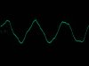
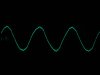
Continue to Site

Welcome to our site!

Electro Tech is an online community (with over 170,000 members) who enjoy talking about and building electronic circuits, projects and gadgets. To participate you need to register. Registration is free. Click here to register now.

  • Welcome to our site! Electro Tech is an online community (with over 170,000 members) who enjoy talking about and building electronic circuits, projects and gadgets. To participate you need to register. Registration is free. Click here to register now.

Output two different sine waves with 16F88 and CCS C?

Status
Not open for further replies.
I don't know why but when I copied the table from excel it got the last 2 values wrong.
Code:
CONST unsigned int SINE_WAVE[32] = {
    7,8,10,11,12,13,13,14,14,14,13,13,12,11,10,8,
    7,6,4,3,2,1,1,0,0,0,1,1,2,3,4,6};

Your 4 bit network should use the same data. Have you got the 1k on bit 3 down to the 8k on bit 0?

Attached is the sine wave. As you can see it is approximate as it's only 4 bit but should become smoother with filtering.

Mike.
 
Last edited:
Thank you for the links about sine wave/dds generation, these ones I haven't seen before (I guess google sometimes misses the "good stuff"), and for the corrected sine wave table.

And I did have the bits/resistors reversed in my 4-bit network so going "backwards" did the trick. I think prior I used a 20 value sine wave table which worked in the old direction and wasn't compatible with the new 32 value table. ;)

I have taken two photos to show the sine wave from a R2R and 4-bit network via a RC filter (50ohm/10uF on both). You can see that the R2R has pretty jagged edges while 4-bit is smoother. This was taken in the DSO mode with avg of 2 on my PM 3394.

So now, should I bother switching to timer1 or is that even possible, to achieve better control of the frequencies (resolution)?

Also, where do I stick the LED flashing so that they flash in the right beat, the interrupt routine?

I also wonder, is it possible to make a gradient transition between the two beats and how would that be done over a specified number of seconds? For example I would like to lower the beat from 11.1Hz to 6.4Hz in 60 seconds or 80 seconds.

I know I have lots of questions and I truly appreciate your help. I want to see this through because I could've simply used an AVR chip and build the circuit as described. But then I would not have learned anything about PIC timers and interrupts as I did now. :)
 

Attachments

  • r2r.jpg
    r2r.jpg
    23.9 KB · Views: 146
  • 4-bit.jpg
    4-bit.jpg
    25.8 KB · Views: 149
You can generate any frequency by calculating the value to add to position. The equation is,

N = F*4.096

So, if you want signal 1 to start at 11.1 Hz then you would calculate the step value as 11.1*4.096 = 45.

In your ISR you could add a time count,
Code:
void interrupt(){
    position+=step;
    PORTB=SineTab[(position>>8)&31];
    position2+=step2;
    PORTA=SineTab[(position2>>8)&31];
    if(timeCount++==20){
        timeCount=0;
        hundreths++;
    }
}

In your main code you could then tween between values.

Code:
StartValue = (int)11.1*4.096; // start frequncy
EndValue = (int)6.4*4.096;    // end frequency
timeSteps = 8000;        // number of 100th of a second
hundreths=0;             // clear 100th counter
While(hundreths<timeSteps){
    //the following needs to use signed values and maybe floats
    step=(EndValue-StartValue)*hundreths/timeSteps+StartValue;
}

If this proves jittery then it would probably be worth switching from 24.8 to 16.16 fixed point calculations.

Mike.
 
Pommie these are excellent, thank you again!

Would you please just clarify for me, we make the start/endvalue 8-bit with the cast and that's where you refer to the possible jitter? The 4.096 factor in the formula, where is that derived from?

Then wouldn't the first value of step be 0 because we are starting with hundreths=0 and that would make an extra jitter as well?

My StartValue/EndValue need to be the actual frequency2 (the one that changes), right? So if the previous value was 199.95Hz (819) I would move up to 204.65 (838) to get the final difference of 11.1Hz-6.4Hz=4.7Hz, from the base frequency1 of 211.91Hz (868)? :)

I'm just not sure what you mean by switching from 24.8 to 16.16 (unsigned vs signed?). Right now step/step2 are long in my code.

Could I also make this as a function instead of being part of the main code?

I assume I will have to tie the LEDs in the interrupt then and drive them directly from there because I do not need the frequency1/frequency2 but their binaural difference? Or is there an easier way for that?

I know, so many questions... :)
 
Sorry, I assumed that int was 16 bit. If int is 8 bit then it should be changed to word/long or whatever is 16 bit.

The first value of step would be StartValue as we add that to the tweened value.

I should have said 16.16 instead of 8.8. What size is long 16 or 32 bit?

The tween calculation could be a function but it would have to be called at least 1 every hundredth of a second. It can possible be slower as humans are not good at picking exact frequencies, too slow and it will sound stepped.

For the LED, I would try,
Code:
void interrupt(){
    position+=step;
    TempB=SineTab[(position>>8)&31];
    PORTB=TempB;
    position2+=step2;
    TempA=SineTab[(position2>>8)&31];
    PORTA=TempA;
    if((TempA-7)+(TempB-7)>0){
        LED=1;
    }
    else{
        LED=0;
    }
    if(timeCount++==20){
        timeCount=0;
        hundreths++;
    }
}

Edit, missed a bit. The 4.096 is derived from the earlier formula. N=F * 500*10-6*32*256.
4.096 = 500*10-6*32*256

Mike.
 
Last edited:
The int in CCS C is 8-bit (int8) while a long is an int16, long long being int32 and float being int32, all except of float are unsigned by default.

What I was hoping to do is have a gradient function as well as a duration one, so that various "sessions" could be played out ie:

play_tone(<freq>, <dur>);
grad_tone(<freq1>, <freq2>, <dur>);
play_tone(<freq>, <dur>);
....

Or even better to have a scripted sequence table converted to suit this code from the output of Gnaural (**broken link removed**...

Here's an enhanced version of the Brain Machine for AVR, http://www.tahina.priv.at/electronics.html#index3h1 and if you peek in the source code the fellow uses DDS-generated audio and converts a session through Perl from Gnaural. I'd like to be able to do something like that ultimately in my project as well.

Thank you.
 
Last edited:
To make the code more functional you could do,
Code:
void PlayTone(long Freq1,long Freq2,long Duration){
signed int32 work;
    hundreths=0;
    While(hundreths<Duration){
        work=Freq2-Freq1;
        work*=hundreths;
        work/=Duration;
        step=work+Freq1;
}


void main(){
    PlayTone(45,45,200);       //play 11.1Hz for 2 seconds
    PlayTone(45,868,500);      //increase to 211.9 over 5 seconds
    PlayTone(868,819,1000);    //play 211.9Hz and change to 200Hz over 10 seconds
}

I think it is better to precalculate the frequency values so as to avoid FP calculations. I added a 32 bit work variable to stop the possibility of overflow and make it signed.

The page you linked to states that the LED should be lit when the 2 signals are out of phase. This can be easily done with,
Code:
    if((TempA&8)!=(TempB&8)){
        LED=1;
    }
    else{
        LED=0;
    }
I suspect that this will produce a beat of twice the required frequency as it effectively lights the LED on each half cycle and the earlier code may be better.

Am I right in assuming that this code works as intended and you are getting the correct frequencies output? It's unusual to write code without any hardware to test it on and even more so for it to work.

Mike.
 
Last edited:
Sorry I should've been more clear about what binaural sounds do.

We create a base frequency, let's say 200Hz and we play it into one ear. Then we create another frequency offsetted from the base by the desired brain wave frequency, let's say 211.1Hz, and play that into the other ear.

The two tones "interfere" in the brain and their difference of 11.1Hz results in the entrainment signal that the brain will start syncing to and resonating in the Alpha state region.

Beta is 13-30Hz, Alpha is 8-13Hz, Theta is 4-8Hz and Delta is 0-4Hz, the first is conscious and alert state, then dreamy, following subconscious and deep unconscious.

By lowering the resonant frequency over a period of time we slowly relax the mind and go into deeper relaxation, of course it all depends what's the final goal. We do not want a subject to fall asleep by resonating in Theta and Delta continuously, so we add a bit of Beta to keep the person awake. :)

So we really never play anything over 30-35Hz difference, and the 200Hz as base is only picked because it's more pleasant than 400Hz which sounds too high pitched.

I have tested the output and I ran into a problem, a jitter or subharmonic noise of sort that occurs. I thought it was my MCU at first but then I swapped output_a and output_b and the same thing happens, so this has to do with TempB computation because TempA is just fine, nice constant tone.

Code:
    position+=step;
    TempB=SineTab[(position>>8)&31];
    output_b(TempB);
    position2+=step2;
    TempA=SineTab[(position2>>8)&31];
    output_a(TempA);

I have no clue why is this happening, I have tried outputting tones on PortA and PortB as per code above as well as both tones on PortB and it still occurs regarding TempB part.

I am using an internal oscillator in the PIC, just trying to have as few components as possible since I'd like to mount the circuit onto the glasses like they did in the original project. Do you think that internal oscillator could be adding these noises because I'm running it at its max?

I will try to record the sound through my soundcard and attach it so you can hear what I mean, it is rather distinct. Here's the full code so far in case you can see something I'm obviously unable to see, I took out the LED and gradient code until this noise issue is resolved:

Code:
#include <16F88.h>
#fuses INTRC_IO,NOWDT,NOPROTECT,NOLVP,PUT
#use delay(clock=8000000)

int timeCount; //int = int8
long TempA, TempB, step, step2, position, position2; //long = int16

CONST unsigned int SineTab[32] = {
    7,8,10,11,12,13,13,14,14,14,13,13,12,11,10,8,
    7,6,4,3,2,1,1,0,0,0,1,1,2,3,4,6};

#INT_TIMER2
void interrupt(){
        position+=step;
        TempB=SineTab[(position>>8)&31];
        output_b(TempB);
        position2+=step2;
        TempA=SineTab[(position2>>8)&31];
        output_a(TempA); 
}

void main(void) {
	setup_oscillator(OSC_8MHZ | OSC_INTRC);   // Use internal 8MHz oscillator 
	set_timer2(0);
	setup_timer_2(T2_DIV_BY_4, 249, 1); // 500us = (1/8000000 * 4 * 4 * 249+1)

        step = 819; // changing frequency
	step2 = 868; // base frequency
	enable_interrupts(INT_TIMER2);
	enable_interrupts(GLOBAL);
	
	while(TRUE)
	{
		delay_us(1);
	}
   
        disable_interrupts(INT_TIMER2);
}

Many thanks!
 
In follow-up, I have tried lowering the internal oscillator frequency to 4MHz without much luck.

I am attaching the two sound recordings from PortA (output_good.mp3) and PortB (output_bad.mp3). What's even more bizzare is that the good sound is fairly uniform but a bit distorted, while the bad sound has jitters but it's quite clear?!?

Both ports run identical 4-bit R-ladders (bit0-bit3: 8k2, 3k9, 2k, 1k tied together with 10k onto gnd) and identical RC filters (50ohm/10uF).

I am at a loss...
 

Attachments

  • output.zip
    305.1 KB · Views: 140
What happens when you output the same frequency (The good one) on both PortA and PortB? As they both the same or is PortB still bad?
 
Is the noise tied to the step value. If you swap the 2 values (819 & 868) does the distortion move to the other channel?

Mike.
 
3dlvr,

You say you have posted all your code but I don't see where you setup the ports. How do TRIS, ANSEL and CMCON get setup?

Mike.
 
Hello,

I have found a reason for the distortions on the good channel - my bad desk illumination. I have mistakenly used a 1K resistor to the ground instead of 10K, in my 4-bit network on the PortA. That's fixed now...

But the problem with the jitter on PortB is still there, I have tested the output of both TempA and TempB values to both ports.
TempA (the good one) sounds just fine, but TempB has jitter on either and both ports regardless.

The compiler uses "standard" mode for IO whereas pins are set to input or output every time they are used. It is less optimized way as it takes 1 byte for every port set to standard IO, but I'm not concerned with optimization right now.

I did try using a "fixed" IO mode where I would declare the ports used in output in my pre-processor directives, but that made no difference, the jitter is still there coming from the TempB variable.

I would rule out a bad MCU because the jitter happens on the PortA when redirected there, not just PortB. This must be something to do with the computation part of TempB then I just can't see what, it seems fairly straight forward?
 
I have just tested something, put the step2 (base frequency) value to be the same, 819 as step (changing frequency) one.

step2 was 868 before and now with 819 I get that jitter on the PortA as well.

So the problem is with the FP calculations or something of sorts, dividing/multiplying with 868 is nice but with 819 is not and so the SineTab produces jitters.

But now what? use float for all, then how would I round all this properly so it does not jitter?
 
I can't understand how 819 can be a problem yet 868 isn't. The only thing I can think is that there is interference between the 119.9 frequency and the 2000Hz frequency.

What happens with 818 and 820?

Are you able to compile assembler as I could knock up a quick asm version to check it isn't a quirk of the compiler.

Mike.
Edit, a possible solution may be to switch to 250uS interrupts and hope the filter sorts out any problems.
 
Another thought, how are you listening to the signals. If it's through your PC then the sample frequency could be interfering with the playback frequency. The glitch is very distinctive, can you see it on a scope?

Mike.
 
Just incase anyone fancies trying this in asm, here it is.
Code:
                LIST    p=16F88
                #INCLUDE <P16F88.INC>
                        
                errorlevel -302
;------------------------------------------------------------------------------  
                        
                __CONFIG _CONFIG1, _CP_OFF & _CCP1_RB0 & _DEBUG_OFF & _WRT_PROTECT_OFF & _CPD_OFF & _LVP_OFF & _BODEN_OFF & _MCLR_ON & _PWRTE_ON & _WDT_OFF & _INTRC_IO
                __CONFIG _CONFIG2, _IESO_OFF & _FCMEN_OFF
                        
;------------------------------------------------------------------------------  
                        
                CBLOCK  0x20            ; Sample GPR variable registers allocated contiguously
Position:2              
Step:2                  
TempB                   
                ENDC    
                        
W_TEMP          EQU     0x7D            ; w register for context saving (ACCESS)
STATUS_TEMP     EQU     0x7E            ; status used for context saving (ACCESS)
PCLATH_TEMP     EQU     0x7F            ; variable used for context saving
                        
;------------------------------------------------------------------------------  
; RESET VECTOR          
;------------------------------------------------------------------------------  
                        
RESET           ORG     0x0000          ; processor reset vector9
                PAGESEL START
                GOTO    START           ; go to beginning of program
                        
;------------------------------------------------------------------------------  
; INTERRUPT SERVICE ROUTINE  
;------------------------------------------------------------------------------  
                        
ISR             ORG     0x0004          ; interrupt vector location
;         Context saving for ISR  
                MOVWF   W_TEMP          ; save off current W register contents
                MOVF    STATUS,W        ; move status register into W register
                MOVWF   STATUS_TEMP     ; save off contents of STATUS register
                MOVF    PCLATH,W        ; move pclath register into W register
                MOVWF   PCLATH_TEMP     ; save off contents of PCLATH register
                        
;------------------------------------------------------------------------------  
; USER INTERRUPT SERVICE ROUTINE GOES HERE  
;------------------------------------------------------------------------------  
                        
                movfw   Step            ;Position+=Step
                addwf   Position,F
                movfw   Step+1
                btfsc   STATUS,C
                addlw   1
                addwf   Position+1,F
                movlw   high GetSine    ;Prepare to get sine value
                movwf   PCLATH
                movfw   Position+1
                andlw   .31             ;TempB=(Position>>8)&31
                call    GetSine
                movwf   TempB
                movwf   PORTB
                        
                bcf     PIR1,TMR2IF
                        
                        
;         Restore context before returning from interrupt  
                MOVF    PCLATH_TEMP,W   ; retrieve copy of PCLATH register
                MOVWF   PCLATH          ; restore pre-isr PCLATH register contents
                MOVF    STATUS_TEMP,W   ; retrieve copy of STATUS register
                MOVWF   STATUS          ; restore pre-isr STATUS register contents
                SWAPF   W_TEMP,F
                SWAPF   W_TEMP,W        ; restore pre-isr W register contents
                RETFIE                  ; return from interrupt
                        
;------------------------------------------------------------------------------  
; MAIN PROGRAM          
;------------------------------------------------------------------------------  
                        
START                   
                bsf     STATUS,RP0
                movlw   0xf0
                movwf   TRISA
                movwf   TRISB
                movlw   b'00000111'     ;	disable comparator
                movwf   CMCON
                movlw   B'01110000'     ;select 8MHz clock
                movwf   OSCCON
                clrf    ANSEL           ;no ADCs
                bcf     STATUS,RP0
                        
                movlw   1<<TMR2ON|b'01'<<T2CKPS0
                movwf   T2CON
                bsf     STATUS,RP0
                movlw   .249
                movwf   PR2
                bsf     PIE1,TMR2IE
                bcf     STATUS,RP0
                        
                movlw   low(.819)
                movwf   Step
                movlw   high(.819)
                movwf   Step+1
                        
                movlw   (1<<GIE|1<<PEIE|0<<TMR0IE|0<<INTE|0<<RBIE|0<<TMR0IF|0<<INTF|0<<RBIF)
                movwf   INTCON          ;		enable Peripheral interupts
                        
                        
;------------------------------------------------------------------------------  
; PLACE USER PROGRAM HERE  
;------------------------------------------------------------------------------  
                        
                GOTO    $
                        
                org     0x0400
GetSine         addwf   PCL,F
                dt      .7,.8,.10,.11,.12,.13,.13,.14,.14,.14,.13,.13,.12,.11,.10,.8
                dt      .7,.6,.4,.3,.2,.1,.1,.0,.0,.0,.1,.1,.2,.3,.4,.6
                        
                END

Mike.
 
Pommie said:
I can't understand how 819 can be a problem yet 868 isn't. The only thing I can think is that there is interference between the 119.9 frequency and the 2000Hz frequency.

What happens with 818 and 820?

Are you able to compile assembler as I could knock up a quick asm version to check it isn't a quirk of the compiler.

Mike.
Edit, a possible solution may be to switch to 250uS interrupts and hope the filter sorts out any problems.

I will try 818 and 820 and report here, as well as 250uS interrupts...
 
Status
Not open for further replies.

New Articles From Microcontroller Tips

Back
Top