Continue to Site

Welcome to our site!

Electro Tech is an online community (with over 170,000 members) who enjoy talking about and building electronic circuits, projects and gadgets. To participate you need to register. Registration is free. Click here to register now.

  • Welcome to our site! Electro Tech is an online community (with over 170,000 members) who enjoy talking about and building electronic circuits, projects and gadgets. To participate you need to register. Registration is free. Click here to register now.

Oscilloscope connected to AC netural

Status
Not open for further replies.

jimg

Member
Hi all, newbie here.

I recently broke down and bought an economical oscilloscope.

I'm working on a DC circuit when the ground is connected directly to the neutral wire of the AC line and was getting some ugly waveforms.

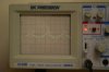
So as a test, I just connected the probe tip and probe ground wire to the neutral AC line and the attached picture shows what I got with probe set on 1x and level at .1 v / grid. It may not be much relative to 120v AC, but its a lot of ripple or noise of whatever relative the the 3V DC supply in my circuit.

The question is, it this normal or is there something wrong with my new scope? I have set the probe compensation dead on. I get this with the probe on 1x or 10, and on both channels.
 

Attachments

  • IMG_0727.jpg
    IMG_0727.jpg
    865.1 KB · Views: 609
I'm a bit confused as to how you're actually connecting it?, but at maximum sensitivity (as it is) you're quite likely to get a few mV of noise.

The scope looks fine!.
 
if that's channel 1, you have it set on what appears to be 5 mV, not .1. so we are talking 12 mV PP. just noise.
 
The large line on the front knob is for variable volts/grid. It is set all the way clockwise for normal operation. The small line on the back knob is the volts/grid setting, and is set for 50 mv or .05v/grid (not .1 as I said above, sorry), so the total is .1v pp. I am connecting both the ground wire on the probe and the tip of the probe together on the neutral ac line. Since the probe tip is connected to the probe ground clip, I would expect to just see a flat line. I do see a flat line until I connect them both to the neutral ac line. So I am rather confused at this point.

I guess the best way to see is try your scope this way to see if you get the same results. (Please don't connect your probe ground clip to the hot side of the ac line, it's not pretty!)
 
Last edited:
If you're connecting the scope to a mains wire?, you need an isolation transformer to feed your scope, or disconnect the earth lead from it (not recommended unless you know what you are doing).
 
So this is normal. Is that the same result you get? Is this some kind of internal scope working thing or is this an actual ripple between the AC line neutral and ground? I tried turning everything in the house off and I can't find the source of the ripple unless it is the scope itself doing it.
 
OK, so you connect probe tip to probe ground and get a straight line, that is good.
You then connect tip and ground to AC neutral and get the horrible mess in the picture.

What I think is happening is that the chassis if the scope is earthed via its mainslead, you are then making a connection to AC neutral with the probe earth and a large current is flowing from the neutral, through the probe cable, through the scope chassis, and out through the scope mains lead to earth.
This is a bad thing to do!:(

Although AC neutral is connected to earth somewhere, that does not mean that the neutral connection at your wall outlet will be at ground potential, there is often a few volts there.

If you must make measurements on this thing which is referenced to AC neutral, there are several things you can do:

Use an isolating transformer so that the DUT is floating and not tied to AC neutral.

Use the two channels of the scope in a differential mode (add + invert), put one probe on the neutral, one probe on the DUT and see the true measurment.

Lift the earth connection from the scope, to let the scope chassis "float".
I DO NOT recommend this method, although there are those around here who do. (Nigel? :rolleyes: )

JimB
 
Thank you. With your warning in mind, I shorted the neutral to the ground right at the outlet and that brought the ripple down to 10mv. Much better. I'll have to look into getting an isolation transformer.
 
You may not have what's referred to as bonded nuetral in your home's AC box. The bonding you are doing at the outlet is way wrong and should be done at the AC breaker box itself. I'd call in an electrician to check over things. The potential exists for massive damage to electronic equipment someday should you be tying AC legs together outside the breaker box..
 
To check measure the voltage between neutral and earth using a multimeter (AC setting), it should read less than 5V.

What you've just done only worked because the scope is probably connected to the same puld socket as your circuit so shorting the neutral to earth has created a common reference.

This isn't really the right way of doing it. What you are doing is creating a huge earth loop, this is bad because it can cause interference (as you've just seen) and it can effect the operation of protective devices such as RCDs.
 
OK. After checking the prices on .8A isolation transformers, I'll just have to live with the noise. Unless there is a thread around here somewhere dealing with lifting the earth connection from the scope in a safe and sane manner?
 
jimg said:
OK. After checking the prices on .8A isolation transformers, I'll just have to live with the noise. Unless there is a thread around here somewhere dealing with lifting the earth connection from the scope in a safe and sane manner?

This is a frequent and hotly debated subject, an un-earthed scope is more dangerous than an earthed one under SOME circumstances, but is considerably safer under OTHER circumstances. Neither is safe under ALL circumstances!.

Personally, I wouldn't consider using an earthed scope, I consider it far too unsafe - and much (most?) of the UK electronics service industry (including some BIG multi-national electronics companies training facilities) feel the same way.

However, earthed or not, you need to fully understand the principles involved, and the problems associated with both methods. For that matter, why are you doing this?.

Essentially, what you're doing at the moment is measuring the voltage drop across part of your electrical wiring! - a classic 'earth loop'.
 
Last edited:
Nigel Goodwin said:
...an earthed scope is more dangerous than an earthed one

just a typo, but for clarity, which are you saying can be more dangerous - the earthed or the unearthed?

Personally, I wouldn't consider using an earthed scope
Again, are you in favor of using the UN-earthed scope or the earthed scope?

like I said - I'm not trying to pick out your grammar, etc - i can't stand it when all someone has to contribute is pointing out speeling erors.
 
Nigel- Thank you for that insight. I'm only considering this because I hate to see that noise in my circuit when I'm trying to get out glitches from other sources. For me it's not a safety issue. I've already blown a fuse and softened up a ground lead on my probe by getting it too close to a hot connection. Would "unearthing" a scope be a simple matter of removing the grounding pin on the plug, or would it entail disconnecting wires internally?
 
JimB calling jimg....

Does your scope have two channels?
Does it have the facility to ADD the two channels together?
Does it have an INVERT switch on one of the channels?

If yes to all these questions, there is a safe, zero cost way of removing the unwanted signal.

JimB
 
OutToLunch said:
just a typo, but for clarity, which are you saying can be more dangerous - the earthed or the unearthed?

Sorry about the typo! - I consider EARTHED scopes more dangerous.

Again, are you in favor of using the UN-earthed scope or the earthed scope?

like I said - I'm not trying to pick out your grammar, etc - i can't stand it when all someone has to contribute is pointing out speeling erors.

I'm in favour of UN-EARTHED scopes - thanks for spotting the typo!.
 
jimg said:
Nigel- Thank you for that insight. I'm only considering this because I hate to see that noise in my circuit when I'm trying to get out glitches from other sources. For me it's not a safety issue. I've already blown a fuse and softened up a ground lead on my probe by getting it too close to a hot connection. Would "unearthing" a scope be a simple matter of removing the grounding pin on the plug, or would it entail disconnecting wires internally?

It's just a matter of removing the earth lead from the plug, all my scopes (both home and work) have non-moulded plugs, so you can simply unscrew the plug and remove the lead. Bear in mind these are all UK 13A plugs, and to show it's not earthed I pull the earth wire back out of the plug so it's clearly visible.

Modern moulded plugs would make it more difficult.
 
Nigel Goodwin said:
I consider EARTHED scopes more dangerous.
I'm in favour of UN-EARTHED scopes.

Ugh! Horrible!
Nigel and I do not agree on this point.

If you MUST unearth a scope, have a special mains cable and only use it when required.
There are other (safer) ways to do the job.

JimB
 
Nigel Goodwin said:
This is a frequent and hotly debated subject, an un-earthed scope is more dangerous than an earthed one under SOME circumstances, but is considerably safer under OTHER circumstances. Neither is safe under ALL circumstances!.
An unearthed scope is fine providing ti's souble insulated, but I haven't seen many of those around.
 
Nigel- Thank you for your patience. I just cut the ground wire of an extension cord and left the green, unattached ground wires hanging out a few inches away from the plug and it worked beautifully. I think I'm still going to have to go inside and see if it's possible to isolate the probe grounds from the case however.

JimB- I understand what you're saying about the two channels. Unfortunately, I'm usually using both and wished I had 3 or 4 more!
 
Last edited:
Status
Not open for further replies.

Latest threads

New Articles From Microcontroller Tips

Back
Top