Continue to Site
Follow along with the video below to see how to install our site as a web app on your home screen.
Note: This feature may not be available in some browsers.
") ..
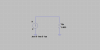
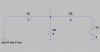
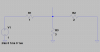
..We can write an equation by assuming a current in the 30 ohm resistor flowing
from left to right. Starting with the 120v source and moving clockwise we get:
120-30*i+2*Va-i*15=0
.