Continue to Site

Welcome to our site!

Electro Tech is an online community (with over 170,000 members) who enjoy talking about and building electronic circuits, projects and gadgets. To participate you need to register. Registration is free. Click here to register now.

  • Welcome to our site! Electro Tech is an online community (with over 170,000 members) who enjoy talking about and building electronic circuits, projects and gadgets. To participate you need to register. Registration is free. Click here to register now.

(old thread/''fixed''issues here)Repairing function generator GW (goodwill) GFG-8020G

Status
Not open for further replies.

fezder

Well-Known Member
Hey all, first off, this is not the same function generator which i have in use, if someone thinks i busted it already. However this which i'm working on is same model, of course different model number....

The fault is simple to describe, it turns on fine, no fuses blown or anything. But, output signal is only DC, regardless of output signal waveform, its pure DC. positive at all else, but in sinewave, it gives small negative voltage.

As for advantage, i have working one where i could measure voltages. There are some fishy results, like the ''heart'' of the instrument, at least what operation manual states, 75107, doesnt have at all same waveforms triangle/square which it should output. There is also constant current sources for both negative and positive voltage for triangle wave generator, which seem to be fine, at least they do the same thing as working one, same voltages and stuff.

Also, i measured voltages from PSU section, (safe-side btw ''isolated'') and there was one thing that caught my eye. There is this transistor, tip32, which takes care of negative voltage regulation -5v. Its base voltage on faulty one is positive, but shouldn't it be negative as it is PNP transistor? I checked it on datasheet, and indeed it needs negative voltage.

I found one faulty component, but i don't think it's what causes the fault, burnt resistor at VCF input (voltage cotrolled frequency). maybe someone just applied overvoltage to that input. But still i'm going to replace that resistor, but that PNP transistor base voltage is strange.

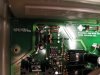
This said, it would be great if someone could lend a hand with this yet another project. Thanks, and i can attach some photos if required/needed
 
Here's the section of psu with fishy transistor.
 

Attachments

  • genis-broken-psu.jpg
    genis-broken-psu.jpg
    91.9 KB · Views: 471
Ok, small update, the psu delivers +/-15v and +/-5v, those i confirmed from working on, reference point was chassis, from bnc connectors. At faulty, voltages were fine, excepct that -5v rail, which was +1.68v.
Seems there is something wrong at -5v regulator, which is that shown in photo.
 
looking at the photo I agree the base ought to be - on the tip 32, it looks like a fairly simple regulator with a zener/cap/resistor.
Measure the voltage on the zener, ought to be around 5.6v, might be worth taking the tip32 out if it measures wrong, also make sure there is actually a - unregulated bus voltage, there probably is if -12v is working.
If the vf input resistor is blackened then theres a good possibility that the waveform generator chip is faulty, or if it goes to an op amp first maybe thats toast.
Wouldnt matter if you had busted your func gen, that sort of thing happens.
Not wishing to sound presumptuous however that is a cheaper end unit probably popular in schools and colleges, so quite possibly someone inexperienced has done something silly with it.

if i recall right, zener voltage was not even near 5.6. it was that in working one, but in that what is broken, zener voltage was around 0.8v. but i'll check it again with tip32 taken out. All other voltage rails +/-15, -12, and +5v were okay. And, as for opamp, voltages were same as working unit.

I just am pretty careful with testing equipment, its like dignity to me to keep them in wokring condition, not to abuse them. Yes, you are right, this is cheap-o model, and from school, so it could be that someone played with it....no wonder after seeing what people do with psu's... but, i'll measure those again, then post results :).
 
took out the tip32c, and zener voltage was 5.6. This is getting strange :S tip32 seems okay, tested it with dmm now when it was out circuit

what could cause tip32's base voltage change to positive? seems strange to me...
 
Last edited:
Replace the tip 32, sounds dead to me, every so often you get one that checks ok but dunt work.
Double check while the tip is out that the collector has more than (or less than) -5v on it so the tranny can actually regulate.
With the tip out the emmitter connection probably will be +, comming from the + rail, if for some reason the tip is open/short or has a dry joint that makes sense, the + rail might be conducting through to the zener which would read forward bias volts around 0.7v.
Was the solder on the tip original?, if not maybe a 'rig doctor' pulled it out and put it back the wrong way.
 
thanks for reply, never thought that transistor can be faulty even if it reads ok. these voltages were when tip32 was out:
base -5.6
collector: -27.6
emitter: +4.6
i used bnc gnd as reference point, if that helps anyway
as for the soldering on tip32, it seems original, as its aligned same way, same pins at same places as working one.

changed the tip32, didn't have that exactly, but tip42, seems equilavent? nevertheless, same situation as before. i did notice that lower capacitor, which is connected to tip32's emitter, is reverse biased when tip32 is out of circuit. does this mean anything? it was around -5v
 
I'd expect those readings, your measuring power from the + rail which bleeds though without the transistor in place.
I think a tip 42 is similar but lower gain.

It sounds like theres a short on the - rail somewhere else within the gen, maybe the original cause of the supply fault.

Are the ic's in sockets, if so unplug them all, is there a link on the - rail to the rest of the gen, if so pull it and see if the - rail from the supply works, another thing that sounds pretty low tech, run the machine for a couple of minutes then carefully touch things (obviously not mains powered items) to see if they are getting warm, if theres a short then something might be getting toasty.
 
oh, forgot to meantion early one thing. there are couple things getting warmer. Those resistors right above tip32, get really hot, much hotter than in working one. And, one ic, (i take a photo of it) sadly, there are no socket for ic's in this model at all. But, i noticed now when i touched those parts which were more or less warmer than should be, they stay cold, but when tip32 is in place, things get warm. And just for safety purposes, i run this by isolation transformer.
I cant see any link at least in quick clance, but i'll look if i can find one. If i got it right, i need to disable negative power rail from the generator, then measure if there is negative voltage? makes sense, if there's short somewhere in negative rail, it will show as negative voltage?
 
I took out the -15v regulator, and there wasn't anymore negative voltage on generator side, measured from -5v, -15v rails and from negative constant current generator.
and also, the negative rail from supply to regulator input was negative, -26v. The regulator i took out was tip32c
 
Follow to the tracks from the hot ic, I suspect they go to the output socket, if so change the ic, maybe its had 240v stuck up it, it does happen.
If the warm ic's are cheap change all of them.
Might also be worth diode testing any diodes and measuring discoloured resistors.
If you dont have the gear to pull ics from plated through holes, snip all the legs off the ic and pull each leg out while heating it with the 'iron one by one.
 
well it wouldn't be surprise if 240v have been at output socket, it does have burnt mark on it. But, i'll see if i can check those diodes, there are none other miscoloured resistors except that which is black.
what kind of gear do you mean? i do have in ''long term loan'' desoldering station, should be enought?
 
Sounds like your geared up allright.

Burn marks on the o/p socket is bad news, expect a bag of blown bits.
 
Status
Not open for further replies.

Latest threads

New Articles From Microcontroller Tips

Back
Top