Continue to Site

Welcome to our site!

Electro Tech is an online community (with over 170,000 members) who enjoy talking about and building electronic circuits, projects and gadgets. To participate you need to register. Registration is free. Click here to register now.

  • Welcome to our site! Electro Tech is an online community (with over 170,000 members) who enjoy talking about and building electronic circuits, projects and gadgets. To participate you need to register. Registration is free. Click here to register now.

Noob: Problem with 900mhz Transmitter and local repeater

Status
Not open for further replies.

CKC123

New Member
DISCLOSURE:

I'm a noob when it comes to RF, so please bear with me if I use the wrong words, or describe things incorrectly. My background is 30 years in software, and doing projects with Arduino/Raspberry PI.

Problem:

I volunteer at a local basketball club, and we use wireless shot clocks. some of the locations we use those clocks in, have a big problem with use/reliability.

I purchased an SDR and was able to identify why there is a problem, and I have some ideas on how to fix it, but I've never really done RF related projects so I'm not sure if I'm on the right track..

Details:

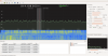
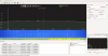
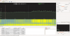
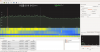
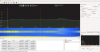
The hand-held transmitters are transmitting at 913.75 mhz
There is a "master" / "slave" relationship between the 2 clocks so they keep themselves in sync. (So 2 transmitters, and 2 receivers )
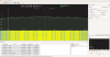
At one location with the SDR & GQRX , I was able to see what appears to be a "repeater" that operates from 907.5 to 923.0 and has some very distinctive patterns in the signals ( each repeating pattern is ~0.5mhz wide)
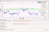
the manufacturer (who I was able to contact initially but has not really been much help since) said the remotes are channel hopping ( but I've seen no evidence of this in the spectrum of the signal it uses)

My Idea:

Since I have no control over the facility and what's being repeated, I was hoping to find a way to:

1) amplify the power of the transmitter somehow?
2) increase the transmitter of the master to the slave?
3) put an external antenna on each of the clocks (but not sure if that also increase the "noise" of the repeater as well)

Any thoughts / direction from the experts here would help..

Thanks in Advance..

D
 
Is the "repeater" that operates from 907.5 to 923.0 in any way connected with your application?

Or do you suspect that the operation of the repeater is incidental and is interfering with the operation of your remotes?

Are your remotes "Part 15" devices?

What country are you in?
 
It's not connected with the device.. I suspect it's there for use of some device in the facility (radios/phone/facility monitoring .. not sure what).

I suspect it's creating "noise" which is drowning out the signal. see attached gqrx screen cap

the controller PDF is at https://www.oes-scoreboards.com/files/spec/ischh_sellsheet.pdf

interesting enough.. there is no FCC id on the controller.. hmmm

I'm located in Canada.
 

Attachments

  • Screenshot from 2016-11-23 21-06-16.png
    Screenshot from 2016-11-23 21-06-16.png
    444 KB · Views: 258
I was able to dig up a bit more..

"Radio OEM Module approved under FCC Part 15.247 and Industry Canada. Contact factory for more details"
 
As a noob to RF, one thing you may not be aware of is that all RF is heavily regulated by governments, including products that use RF, and those of us that work within those regulations are trained to comply or perhaps feel morally obligated to work within the law. The reason that RF is heavily regulated is simply because nothing RF would work if there was no traffic cop to keep it all in order. This is something to keep in mind as we offer advice.

It is very likely that your shot clocks use wireless that is what is called "license-free", meaning the user doesn't need a license to operate them. There is an understanding, a contract if you will, between the manufacturer and the government (of most countries) that as long as the manufacturer builds their products to meet certain rules, then they are allowed to sell them to anyone as license-free. This is really nice and convenient, but this freedom from licensing comes with a price, and that is that the technical limits for such devices don't allow them much range. These technical limits include that they cannot transmit more than a certain, relatively small, amount of power, that they cannot be modified by the user, that they cannot be capable of changing-out antennas, and, the biggest restriction of all, they must suck it up when they receive interference. By this I mean that they have no protection under law from any other users of the radio spectrum. In the United States, the technical rules for license-free devices are called the Part 15 rules (as they are Part 15 of Title 47 of the Code of Federal Regulations) and so we call this kind of device a Part 15 device.

So much for the lecture, now about those shot clocks. Yes, if you have considerable RF circuit expertise, anything can be modified to improve link performance by adding better antennas, or by increasing transmitter power, but these things are not easy. One reason is because part 15 devices usually are not modular, and by this I mean that they don't make it easy to change antennas, or amplifiers, because they are not allowed to. And adding RF power is technically very tricky to do. Let's consider other ideas instead. The most powerful thing you can do is put some distance between your devices and the ones that are interfering with you, so first thing to do is identify where these interfering transmitters are. This is usually done by doing some RF direction-finding. Once you know where they are, the most useful thing you can do is move your shot clock equipment, or their equipment away or apart somehow. Putting some walls and floors between can be helpful too. The other options open to you are choosing channels or hopping sequences (if applicable) between you and the interferers so that everyone can get along without trouble. For example, sometimes it is possible for a frequency hopping device, which it sounds like your interferer is despite what you see on your analyzer, to be programmed to avoid certain channels. Perhaps, if your shot clocks are single channel devices they can be programmed to operate on these selected quiet channels?
 
Last edited:
RadioRon:

actually, I was aware of the band they operate in and the issues around it being "license free" and having to deal with conflicting devices.. your reference to the ability to "modify" them as per the rule, I was not aware of. Thanks!

with regards to the location. that's a no go.. so one aspect I didn't mention (yet) was the location. there are 3 "gyms" in the facility (Large single building split into 3 courts with flexible dividers) , only 2 of them have problems with the shot clocks.. using the SDR I was able to determine that the signal is strongest on the side of the gym which has the most problems.. so moving aware from the source of the signal is not possible.

With regards to the channels.. the manufacturer does have a version which supports 2.4Ghz, but we also have problems with those as well (before I got the SDR, I suspected it was the spectators and people turning on thier hotspots which was causing those models to have problems as well.. so in short.. both versions have problems.. )

is there a way to "jump" the frequency out of the range it's in now by modifying the circuit?
 
Usually the frequency is synthesized and is coded into the device in flash or similar. Many devices allow their users to select one of a list of frequencies, or if they are hopping, a different hop sequence. Does you shot clock have any alternate channels it can work on? Obviously you would want to try those, and you would have by now I guess.
Are you able to discuss this with the owners of the other device? Perhaps it can be adjusted to different channels or different hop sequences.
 
There are alternate frequencies ("A" through "D") but they are not user selectable, and require us to send the shotclocks/remotes back to the manufacturer. (we have 4 of them one on each frequency)

right now I only had access to the one device, but I'm going to try to get into the office to see the frequencies on the others.. from what I understand they are "close" to the others.. so nothing that is outside the range of the repeater in the building (but I can confirm once I can get all 4 to check the frequencies).
 
Looking at the waterfall and spectral display, I do not see what you think is the "repeater". Can you repeat the run with a wider bandwidth so we can see the "edges" of the spectrum attributable to the repeater? Ideally, catch a spectrum where one of your transmitters is active at the same time as the repeater.
 
I agree, Mike. The spectrum looks to me like it could well be a hopping device, but that depends on how slowly the spectrum was acquired and how fast the hopper operates. Most hoppers tend to look like direct sequence spread spectrum on an analyzer if they are hopping quickly, but slow hoppers, those that hop once every few hundred milliseconds are more confusing and look a bit of a mish mash depending on when you capture their spectrum. On the other hand, the spectrum also looks a bit like what you would see if the analyzer dongle front end or A/D converter was overloaded by a narrow or wide bandwidth signal, but hard to say.

The plot is from an FFT analyzer which means that maybe it is taking a pretty big slice of time, I can't tell from the screen shot.
 
So a gold mine of info here.. I was able to get the shotclock to the location tonight, as well as I opened up the remote and found some interesting things

1) There are some pictures showing the "background" " transition" and "signal" for both the low and high end. "Start" of the repeater at 907.5 up to 923 (backgrounds so the complete clean background) there are also to screen shots showing the overlap of the remote and the repeater.

2) The remote is using a Digi International 9XCite 9600 baud board.. which has a mounting point for an external antenna !! I managed to find the technical docs for the boards
https://www.digi.com/support/productdetail?pid=3238

so I guess my first to look at would be to put an external antenna on it and see what happens.. with that in mind I have a few questions on the antenna

1) based on the way the board is mounted in the remote, I would have to rotate it 90 degree from the pictures in the manuals.. is this a problem?
2) are there any specs on the antenna I should be looking for (900mhz and 50 ohm based on the doc.. but not sure if there is more..)

Some other things now come to mind..

I noticed that the board use UART to connect.. and I have a USB/UART I'm guessing I can hook it up and see the serial message it's sending between the remote and the clock..
 

Attachments

  • VN_LOW_BG_Screenshot from 2016-11-30 20-23-00.png
    VN_LOW_BG_Screenshot from 2016-11-30 20-23-00.png
    380.1 KB · Views: 251
  • VN_Low_Screenshot from 2016-11-30 20-22-44.png
    VN_Low_Screenshot from 2016-11-30 20-22-44.png
    386.4 KB · Views: 248
  • VN_High_Screenshot from 2016-11-30 20-23-28.png
    VN_High_Screenshot from 2016-11-30 20-23-28.png
    405.3 KB · Views: 250
  • VN_High_BGScreenshot from 2016-11-30 20-23-48.png
    VN_High_BGScreenshot from 2016-11-30 20-23-48.png
    401.9 KB · Views: 245
  • VN_remote_Screenshot from 2016-11-30 20-28-29.png
    VN_remote_Screenshot from 2016-11-30 20-28-29.png
    397.4 KB · Views: 242
  • VN_PEAK_REMOTE_Screenshot from 2016-11-30 20-34-41.png
    VN_PEAK_REMOTE_Screenshot from 2016-11-30 20-34-41.png
    88.1 KB · Views: 249
  • remote.jpg
    remote.jpg
    1.2 MB · Views: 254
Double Bingo.

Found the exact problem when you compare the FM modulated signal in a "clean" (home) environment and at the location... Note: as per the documentation the signal is NOT repeated, and has a CRC ..

You can see a clean signal, (home) and the general repeater signal at the location.. then you can see the actual overlap/interference on the Signal 1 and signal 2 screen captures.. now it's obvious why it's interferring..

still not sure how to solve it though.
 

Attachments

  • HOME_Signal.png
    HOME_Signal.png
    412.6 KB · Views: 249
  • VN_repeater.png
    VN_repeater.png
    1.6 MB · Views: 252
  • VN_Signal1.png
    VN_Signal1.png
    426.2 KB · Views: 251
  • VN_Signal2.png
    VN_Signal2.png
    432.1 KB · Views: 234
  • VN_Signal2_zoom.png
    VN_Signal2_zoom.png
    323.3 KB · Views: 233
Status
Not open for further replies.

New Articles From Microcontroller Tips

Back
Top