Electro Tech is an online community (with over 170,000 members) who enjoy talking about and building electronic circuits, projects and gadgets. To participate you need to register. Registration is free. Click here to register now.
Welcome to our site! Electro Tech is an online community (with over 170,000 members) who enjoy talking about and building electronic circuits, projects and gadgets. To participate you need to register. Registration is free. Click here to register now.
Could you maybe put pads under that dip switch so that we have the option of using 0.1 inch headers and jumpers instead of an expensive DIP switch, please?
Could you maybe put pads under that dip switch so that we have the option of using 0.1 inch headers and jumpers instead of an expensive DIP switch, please?
The Junebug only programs / debugs 5V parts including many EEPROMs. The genuine PICkit2 has the clamps and programmable VDD parts for 3.3V PICs.
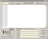
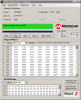
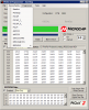
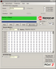
Just testing the Junebug 16F88 using the UART Tool in the PICkit 2 software, this is all possible by only turning off the Tutor switches and turning on the TX & RX switches.
And about the 3D drawing thanks, they did take awhile but since I have a large library of parts it now only takes a couple of hours.
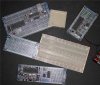
The last photo is some of the LAB-EASY boards. These are teriffic for prototyping with breadboard.
Well if you make hundreds or thousands of PCBs they can be pretty cheap. The blue or any color aside from standard green adds about $0.50 to each PCB. Other cool standard colors are Red, Black, Yellow, White.
Get yourself a 18F2550 and either 16F88 or 18F1320.
I've been reviewing the 18F1320 and 16F88 pinouts with the firefly and I may remove the 16F88 option from the design. The two PICs have very different hardware I/O options.
Opinions?
Edit the images have been updated to show the new design. The 18F1320 has no MSSP or SSP so I disconnected it from the EEPROM (also makes it a more common 8 position dip)
It is (the EEPROM) still connected to the PK2 and may have to be removed when not in use.
If you want a 16F88 tutor the original Firefly will work with this kit too.
The 18F family has the advantage of a dominant single compiler. (no proof) The student version Microchip C compiler. It makes documentation/support for C much easier.
Three breakpoint are nice to have on board used for teaching/learning/experimenting.
If the following makes sense I would keep the 24LCxxx socket.
The PK2 connector duplicates the signals on the "ICD2/Inchworm style" 2x5 ICSP connector. The PK2 connector would make it easier to use with Microchips target boards.
Most people using JuneBug will be using your targets or targets they build. Most people with Microchip target boards will have a Microchip PicKit rather then a JuneBug.
It is easy enough to make a 2x5 to 1x6 adapter for the few who want to use a JuneBug with a target that has 1x6 PK2 style connector.
The PK2 uses pin 6 as AUX, with it the PK2 can program many I2C, SPI, Microwire EEPROMs.
In the land of PIC ICDs there are at least 3 ICD connector types. Official are RJ11 (phone type) and 6 pin inline, many clones including mine use a 2x5 IDC style. The RJ11 is great for Microchip development boards but not so nice for breadboarding, the 6 pin inline is thin and small, great for the PK2 case and good for breadboarding but does not feel very robust and headers fall out of it with only the slightest tug.
For now I'll leave the 24LCxxx socket there, I'll wire it last just incase.
Here's a snippet from the PK2 readme file about EEPROMs and the wiring.
> Serial EEPROM support:
24LC I2C bus devices:
Bus Speed-
400kHz with Tools -> Fast Programming checked
100kHz with Tools -> Fast Programming unchecked
NOTE: Bus pullups are required for all
programming operations. 400kHz requires
2k Ohm pullups.
Ax Chip Select checkboxes-
These are only enabled for devices that support
address chip selects, and allow programming of
multiple devices on the same bus.
Connections for 24LC devices
---------------------------------------
PICkit 2 Pin 24LC Device Pin (DIP)
(2) Vdd 8 Vcc
(3) GND 4 Vss
(5) PGC 6 SCL (driven as push-pull)
(6) AUX 5 SDA (requires pullup)
7 WP - disabled (GND)
1, 2, 3 Ax pins
Connect to Vdd or GND per
datasheet and to set address
25LC SPI bus devices:
Bus Speed-
~925kHz with Tools -> Fast Programming checked
~245kHz with Tools -> Fast Programming unchecked
Connections for 25LC devices
---------------------------------------
PICkit 2 Pin 25LC Device Pin (DIP)
(1) VPP 1 nCS
(2) Vdd 8 Vcc
(3) GND 4 Vss
(4) PGD 2 SO
(5) PGC 6 SCK
(6) AUX 5 SI
7 nHOLD - disabled (Vdd)
3 nWP - disabled (Vdd)
93LC Microwire bus devices:
Bus Speed-
~925kHz with Tools -> Fast Programming checked
~245kHz with Tools -> Fast Programming unchecked
Connections for 93LC devices
---------------------------------------
PICkit 2 Pin 93LC Device Pin (DIP)
(1) VPP 1 CS
(2) Vdd 8 Vcc
(3) GND 5 Vss
(4) PGD 4 DO
(5) PGC 2 CLK
(6) AUX 3 DI
7 PE - enabled (Vdd)
6 'C' Device ORG
Set to select word size
I was unaware of the use of the AUX signal. I think you can still have your cake and eat it too.
The problem is that an adaptor board which hooks to the 2x5 would lack the AUX signal. Not a problem. Put a single wire on the adaptor board that the user hooks to a new connector on JuneBug. Have that new connector carry the AUX singnal. Could be a 1x1 or 1x2 pin header and the placement should not be critical. Can you find a spot for it?
Edit: I noticed that sparkfun has added little wires with sockets on both ends that push over header pins. Has anyone figured out what the sockets are called or know a part number?
**broken link removed** Junk edited out by author.
Done, sounds good to me. I was just playing with the 8 pin socket but the 1x6 PK2 connector will fit fine.
Edit I've added a pair of the 1x6 connectors, just incase you want to use a RA connector and not have it hang too far off the PCB, refresh your browser and see it in the first message in this thread.
Be careful when buying RJ-11 connectors and cable assemblies if you actually need all six conductors. It's my understanding that RJ-11 and RJ-12 are physically the same connector style, but the RJ-11 only uses and supplies the middle four pins and conductors where the RJ-12 supplies all six pins and conductors.
The kit has no provision for the RJ-12 like the real ICD2 has. Junebug uses a 2x5 IDC connector (like most clone ICDs) plus now has the 1x6 as seen on the PICkit 2.
Edit the final 3D picture and PCB layout have been posted here. To see them you must manually refresh your browser.
This site uses cookies to help personalise content, tailor your experience and to keep you logged in if you register.
By continuing to use this site, you are consenting to our use of cookies.