Continue to Site

Welcome to our site!

Electro Tech is an online community (with over 170,000 members) who enjoy talking about and building electronic circuits, projects and gadgets. To participate you need to register. Registration is free. Click here to register now.

  • Welcome to our site! Electro Tech is an online community (with over 170,000 members) who enjoy talking about and building electronic circuits, projects and gadgets. To participate you need to register. Registration is free. Click here to register now.

negative values using adc

Status
Not open for further replies.
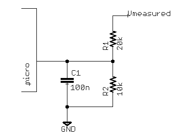
i was able to successfuly read the adc values from 0 to 4v using microcontroller. Now requirement has come to read also from negative 0 to 4. how to read with adc I was finding some voltage divider circuit. can you please help me to find the exact circuit.
 
An opamp can be used to shift or invert a signal. Need to have much more info from you before suggesting a circuit.
 
An opamp can be used to shift or invert a signal. Need to have much more info from you before suggesting a circuit.
He mentions that in his "other" thread.... If the two threads become intertwined, I'll join them...

Isn't google easy!!

A crass voltage divider for +15 / -15... just change the ratio of R1 and R2
int-read-0-15-v.png
 
sorry for the delay iam searching for the details of the sensor and schematics as soon as I get it I will post it. I really need the schematic diagram for this.
 
sorry for the delay iam searching for the details of the sensor and schematics as soon as I get it I will post it. I really need the schematic diagram for this.

And we need things like what supply voltages do you have available, how stable are the supplies, the frequency response of the sensor, what minimum input impedance the sensor can drive, sample rate of the ADC, etc.
 
He mentions that in his "other" thread.... If the two threads become intertwined, I'll join them...

Isn't google easy!!

A crass voltage divider for +15 / -15... just change the ratio of R1 and R2
int-read-0-15-v.png
That voltage divider is not suitable for feeding negative voltages into the microcontroller ADC, unless the microcontroller is powered from a split rail, e.g. ±2.5V. If you add a third resistor between the ADC pin and a stable positive voltage (e.g. VCC), you can measure both positive and negative voltages.
 
Hi,

I have to agree, you need a BIASED voltage divider, biased with a positive voltage. The positive voltage is required so that when the input is minus volts the output is close to zero, and the uC code interprets that again as a negative, scaled voltage.
 
hi Al,
We do not know the impedance of the +/-15V signal source, which is important if we wish to maintain linearity over the Vin input range.
E
 
That voltage divider is not suitable for feeding negative voltages into the microcontroller ADC, unless the microcontroller is powered from a split rail, e.g. ±2.5V. If you add a third resistor between the ADC pin and a stable positive voltage (e.g. VCC), you can measure both positive and negative voltages.
It works though!!! I tested it... The reason I tested it is because I thought the same as you....
 
hi Al,
We do not know the impedance of the +/-15V signal source, which is important if we wish to maintain linearity over the Vin input range.
E

Hello there Eric,

What do you mean here? What kind of impedance do you expect from the +/- 15v source? Any resistance will maintain linearity, but we could loose a lot of range, if that's what you mean.
 
It works though!!! I tested it... The reason I tested it is because I thought the same as you....

Hi Ian,

How did you get an ADC to read a negative signal without some positive bias?
 
It works though!!! I tested it... The reason I tested it is because I thought the same as you....

hi Ian,
The circuit you posted will give +/-5V swing from a +/-15V source, but how will a MCU's ADC, assuming the MCU is powered from +5V, handle the -5v range.?
E
 
Hello there Eric,

What do you mean here? What kind of impedance do you expect from the +/- 15v source? Any resistance will maintain linearity, but we could loose a lot of range, if that's what you mean.

hi Al,
That is what I mean, we must know his source impedance if we are to post a circuit showing divider values.
E
 
hi Ian,
The circuit you posted will give +/-5V swing from a +/-15V source, but how will a MCU's ADC, assuming the MCU is powered from +5V, handle the -5v range.?
E
Don't ask me.... +15 gives 4.6v and -15 gives 0v...
 
Hi all,

a. I have attached the circuit from sensor to ADC of micro this part of the circuit is part of PCB and unfortunately i cannot modify this additional circuit i have to interface with this.
b. The data sheet of the ADC of the micro.
c. The data sheet of the sensor.
The micro works on 5V power source. I have programmed the ADC for 12bit. Now i want to read the sensor voltages from -4V to +4V which are below the 5V source. Please also suggest me some circuit in case any new sensor range is from -10V to +10V or any generic range.

Thanks in advance.
I had little difficulty attaching the docs, but finally i could do it.
Schematic.png
 

Attachments

  • upload_2015-6-16_21-43-9.png
    upload_2015-6-16_21-43-9.png
    6.8 KB · Views: 238
  • HTA 100...1000-S.PDF
    536 KB · Views: 227
  • ADC_micro.pdf
    131.6 KB · Views: 371
Don't ask me.... +15 gives 4.6v and -15 gives 0v...

Is the output of the divider connected to a PIC's ADC input.?
If yes, then its the PIC's internal clamp diode thats sinking the -Vinput range.

Can you post the circuit showing the resistor values that gives +15 gives 4.6v and -15 gives 0v.
 
hi e78,
I would suggest a rail to rail OPA configured to level shift the +/-10V signal to say 0V thru +5V, assume that +2.5V input to the ADC is equivalent to 0V input.
The PIC program could then output the corrected +/- ADC values.
E

EDIT:
This is one option.
 

Attachments

  • AAesp04.gif
    AAesp04.gif
    37.4 KB · Views: 248
Last edited:
Can you post the circuit showing the resistor values that gives +15 gives 4.6v and -15 gives 0v.
I built the same one as the one posted!!! I didn't connect pic!! I connected to an MCP3002 then to the pic.. I was quite surprised with the result!!
 
Status
Not open for further replies.

New Articles From Microcontroller Tips

Back
Top